


34
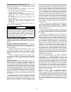
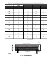
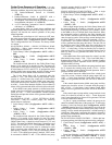
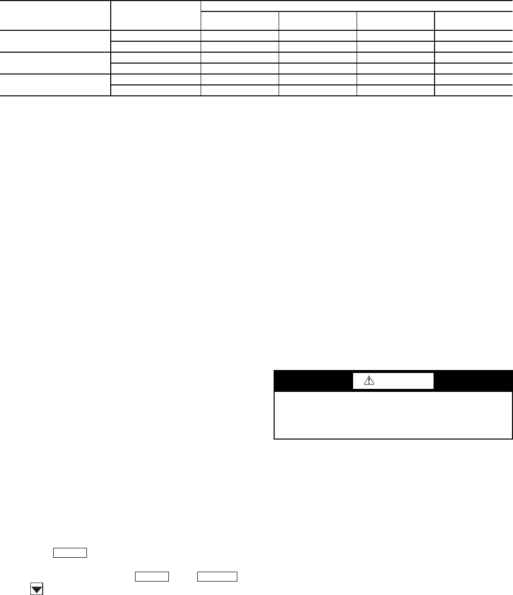
Table 21 — Control Methods and Cooling Set Points
*Dual set point switch input used. CSP1 used when switch input is open. CSP2 used when switch input is closed.
†Cooling set point determined from 4 to 20 mA input to energy management module (EMM) to terminals TB6-3,5.
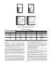
4 TO 20 mA INPUT — Unit operation is based on an external
4 to 20 mA signal input to the Energy Management Module
(EMM).
Low Sound Mode Operation — All models are fac-
tory configured with the Low Sound Mode disabled. In the
Configuration mode under sub-mode OPT2, items for Low
Sound Mode Select (Configuration
OPT2
LS.MD), Low
Sound Start Time (Configuration
OPT2
LS.ST), Low
Sound End Time (Configuration
OPT2
LS.ND) and Low
Sound Capacity Limit (Configuration
OPT2
LS.LT) are
factory configured so that the chiller always runs as quietly as
possible. This results in operation at increased saturated con-
densing temperature. As a result, some models may not be able
to achieve rated efficiency. For chiller operation at rated effi-
ciency, disable the low sound mode or adjust the low sound
mode start and stop times accordingly or set both times to
00:00 for rated efficiency operation 24 hours per day. In addi-
tion, the low sound capacity limit can be used to reduce overall
chiller capacity, if required, by limiting the maximum to a user-
configured percentage.
Heating Operation — The chiller can be used for pump
outputs or optional factory-installed hydronic system operation
can be utilized for heating applications. The heating mode is
activated when the control sees a field-supplied closed switch
input to terminal block LVT-19,20. The control locks out cool-
ing when the heat relay input is seen. A field-supplied boiler re-
lay connection is made using heat relay and alarm relay con-
tacts. Factory-installed ‘BOILER’ connections exist in the con-
trol panel near LVT for these applications. Alarms and alerts
A189 through A202 are active during heating operation.
Service Test (See Table 4) — Both main power and
control circuit power must be on.
The Service Test function should be used to verify proper
operation of condenser fan(s), compressors, minimum load
valve solenoid (if installed), cooler pump(s), EXVs, and re-
mote alarm relay. To use the Service Test mode, the Enable/
Off/Remote Contact switch must be in the OFF position. Use
the display keys and Table 4 to enter the mode and display
TEST. Press twice so that OFF flashes. Enter the
password if required. Use either arrow key to change the TEST
value to the ON position and press . Press
and the button to enter the OUTS or COMP sub-mode.
Test the condenser fans, cooler pump(s) and alarm relay by
changing the item values from OFF to ON. These discrete
outputs are then turned off if there is no keypad activity for
10 minutes. Use the arrow keys to select the desired percentage
when testing expansion valves and Motormaster
®
V controller.
When testing compressors, lead compressor must be started
first. All compressor outputs can be turned on, but the control
will limit the rate by staging one compressor per minute. Com-
pressor unloaders and hot gas bypass relays/solenoids (if in-
stalled) can be tested with the compressors on or off. The relays
under the COMP mode will stay on for 10 minutes if there is
no keypad activity. Compressors will stay on until they are
turned off by the operator. The Service Test mode will remain
enabled for as long as there is one or more compressors run-
ning. All safeties are monitored during this test and will turn a
compressor, circuit or the machine off if required. Any other
mode or sub-mode can be accessed, viewed, or changed during
the TEST mode. The MODE item (Run Status
VIEW) will
display “0” as long as the Service mode is enabled. The TEST
sub-mode value must be changed back to OFF before the chill-
er can be switched to Enable or Remote contact for normal
operation.
Optional Factory-Installed Hydronic Pack-
age —
If the chiller has factory-installed chilled fluid pumps,
specific steps should be followed for proper operation.
The pump(s) in the hydronic package come factory
pre-wired into the main unit power supply/starter. In order to
check proper pump rotation, use the Service Test function to
test the condenser fans and observe them for proper rotation. If
fans turn correctly, the pumps will rotate correctly. Clockwise
rotation of the pump motor cooling fans can also be used to de-
termine that pumps are rotating correctly.
Use Service Test function to test operation of pumps. Verify
that the flow switch input is made when the pump is running.
For dual pump hydronic systems, the control only uses one
pump at a time. Consult the Installation Instructions supplied
with this chiller and use the circuit setter balancing valve
installed in hydronic package to adjust fluid flow rate.
Cooler Pump Control — The AquaSnap® 30RAP ma-
chines equipped with a factory-installed pump package are
configured with the Cooler Pump Control (Configura-
tion
OPT1
CPC) = ON.
Machines not equipped with a pump package are config-
ured with the cooler pump control OFF. It is recommended that
the machine control the chilled water pump. If not, a 5-minute
time delay is required after the command to shut the machine
down is sent before the chilled water pump is turned off. This is
required to maintain water flow during the shutdown period of
the machine.
With or without this option enabled, the cooler pump relay
will be energized when the machine enters an ON status (i.e.,
On Local, On CCN, On Time). An A207 - Cooler Freeze
Protection Alarm, will energize the cooler pump relay also, as
an override. The cooler pump relay will remain energized if the
machine is in MODE 10 – Minimum Off Time.
CONTROL
TYPE
(CTRL)
OCCUPANCY
STATE
COOLING SET POINT SELECT (CLSP)
0
(single)
1
(dual, switch)
2
(dual, occ)
3
(4 to 20 mA)
0 (switch)
Occupied ON,CSP1 ON* ON,CSP1 ON†
Unoccupied ON,CSP1 ON* ON,CSP2 ON
2 (Occupancy)
Occupied ON,CSP1 ON* Illegal ON†
Unoccupied OFF OFF Illegal OFF
3 (CCN)
Occupied ON,CSP1 ON* ON,CSP1 ON†
Unoccupied ON,CSP1 ON* ON,CSP2 ON†
ENTER
ENTER
ESCAPE
CAUTION
Operation of pump in wrong direction, even for a few
seconds, can cause irreversible damage to pump impeller
and housing. Always verify correct wiring/pump rotation
before operation.