


I
CONTENTS
CONTENTS
1. WIRING 1
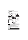
1.1 Standard connection diagram and terminal specifications ........... 2
1.1.1 Standard connection diagram ......................................................................... 2
1.1.2 Explanation of main circuit terminals............................................................... 3
1.2 Main circuit terminals.................................................................... 7
1.2.1 Terminal block layout ...................................................................................... 7
1.2.2 Cables, wiring length, and crimping terminals................................................. 8
1.2.3 Wiring instructions........................................................................................... 9
1.2.4 Selection of peripheral devices ..................................................................... 10
1.2.5 Leakage current and installation of earth (ground) leakage circuit breaker .. 11
1.2.6 Power-off and magnetic contactor (MC)........................................................ 15
1.2.7 Regarding the installation of the reactor........................................................ 16
1.2.8 Regarding noise (EMI) and the installation of a noise filter........................... 17
1.2.9 Earthing (Grounding) precautions ................................................................. 18
1.2.10 Power supply harmonics ............................................................................... 19
1.2.11 Harmonic suppression guideline ................................................................... 20
1.2.12 Inverter-driven 400V class motor .................................................................. 24
1.3 How to use the control circuit terminals...................................... 25
1.3.1 Terminal block layout .................................................................................... 25
1.3.2 Wiring instructions......................................................................................... 25
1.3.3 Changing the control logic............................................................................. 26
1.4 Input terminals............................................................................ 28
1.4.1 Run (start) and stop (STF, STR, STOP) ....................................................... 28
1.4.2 Connection of frequency setting potentiometer and
output frequency meter (10, 2, 5, 4, AU)....................................................... 31
1.4.3 External frequency selection (REX, RH, RM, RL)......................................... 32
1.4.4 Indicator connection and adjustment (FM).................................................... 34
1.4.5 Control circuit common terminals (SD, 5, SE)............................................... 36
1.4.6 Signal inputs by contactless switches........................................................... 36
1.5 How to use the input signals
(assigned terminals AU, RM, RH, STR) ..................................... 37
1.5.1 Multi-speed setting (RL, RM, RH, REX signals):
Pr. 60 to Pr. 63 setting "0, 1, 2, 8"
Remote setting (RL, RM, RH signals):
Pr. 60 to Pr. 63 setting "0, 1, 2"..................................................................... 37
1.5.2 Second function selection (RT signal): Pr. 60 to Pr. 63 setting "3" ............... 37
1.5.3 Current input selection "AU signal": Pr. 60 to Pr. 63 setting "4" .................... 37
1.5.4 Start self-holding selection (STOP signal): Pr. 60 to Pr. 63 setting "5" ......... 38
1.5.5 Output shut-off (MRS signal): Pr. 60 to Pr. 63 setting "6" ............................. 38