


48
Handling of the RS-485 connector
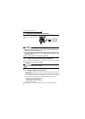
1.7 Handling of the RS-485 connector
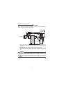
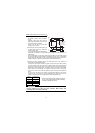
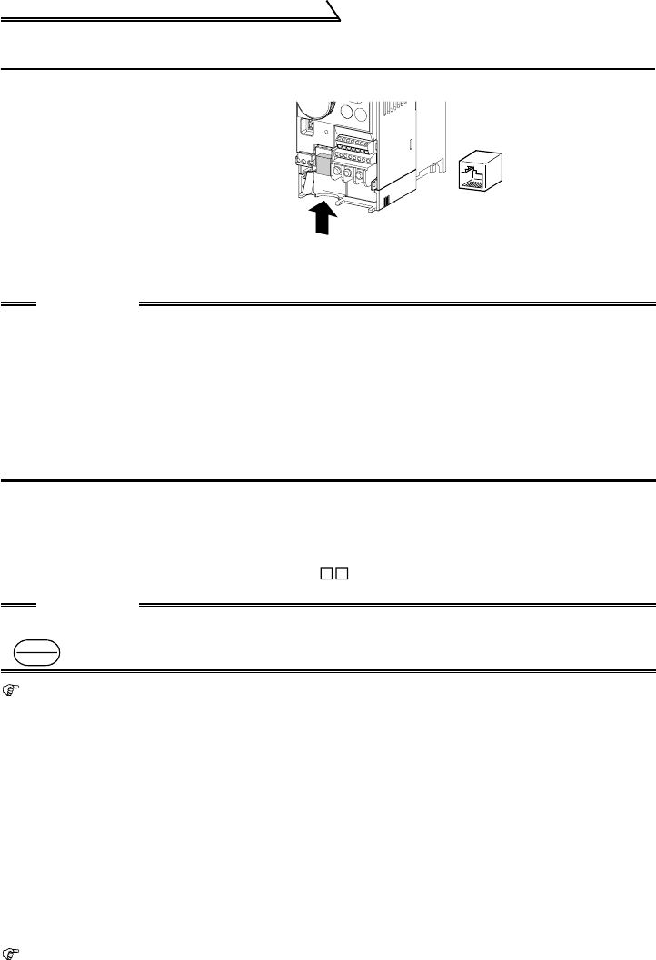
1.7.1 Connection of the parameter unit (FR-PU04)
When connecting the parameter unit to the RS-485 connector, use the optional
parameter unit connection cable (FR-CB2 ).
Refer to page 162 for the parameters related to parameter unit setting.
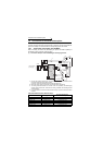
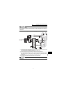
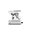
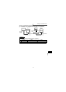
1.7.2 Wiring of RS-485 communication
Use the RS-485 connector to perform communication operation from a personal
computer etc.
When the RS-485 connector is connected with a personal, FA or other computer
by a communication cable, a user program can run and monitor the inverter or
read and write to the parameters. For parameter setting, refer to page 141.
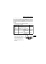
•Conforming standard: EIA-485 (RS-485)
•Transmission format: Multidrop link
•Communication speed: Max. 19200bps
•Overall extension: 500m
Refer to page 141 for the setting related to RS-485 communication operation.
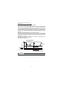
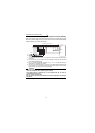
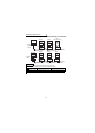
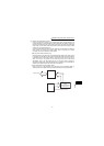
<RS-485 connector pin layout>
View A of the inverter (receptacle
side)
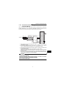
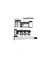
CAUTION
1. Do not plug the connector to a computer LAN port, fax modem socket,
telephone modular connector etc. The product could be damaged due to
differences in electrical specifications.
2. Pins 2 and 8 (P5S) are provided for the parameter unit power supply. Do not
use them for any other purpose or when making parallel connection by RS-
485 communication.
3. Refer to page 143 for the communication parameters.
CAUTION
When the parameter unit is used, the operation other than the stop key
( ) of the operation panel is disabled.
8) to 1)
1) SG
2) P5S
3) RDA
4) SDB
5) SDA
6) RDB
7) SG
8) P5S
View A
View A
STOP
RESET