


198
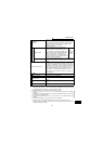
Specification list
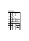
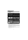
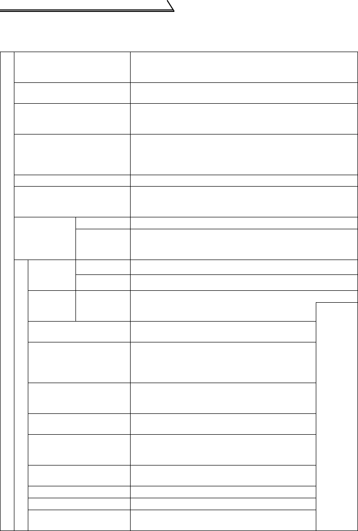
4.1.2 Common specifications
Control specifications
Control method
Selectable between Soft-PWM control and high carrier
frequency PWM control, V/F control or automatic torque
boost control are selectable.
Output frequency
range
0.5 to 120Hz (starting frequency variable between 0 and
60Hz)
Frequency
setting
resolution
5VDC input: 1/500 of max. set frequency, 10V,
4 to 20mADC input: 1/1000 of max. set frequency
Digital input: 0.1Hz (less than 100Hz), 1Hz (100Hz or higher)
Frequency
accuracy
Analog input: Within ±1% of max. output
frequency(25
°C±10°C)
Digital input: Within ±0.5% of set output frequency (when set
by the setting dial)
Torque boost Manual torque boost, automatic torque boost
Acceleration/deceleration
time setting
0, 0.1 to 999s (acceleration and deceleration can be set
individually), linear or S-pattern acceleration/deceleration
mode can be selected.
Braking torque
Regeneration 15% torque/continuity
DC
injection
brake
Operation frequency (0 to 120Hz), operation time (0 to 10s),
operation voltage (0 to 15%)
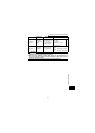
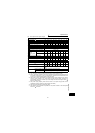
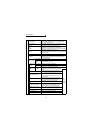
Input signals
Frequency
setting
signal
Analog input 0 to 5VDC, 0 to 10VDC, 4 to 20mA
Digital input Entered from operation panel
Start signal STF, STR
Forward and reverse rotation, start signal
automatic self-holding input (3-wire input) can be
selected.
Use
Pr. 60 to
Pr. 63 for
selection
Reset
Reset the alarm output when the protective
function is activated
Multi-speed selection
Up to 15 speeds can be selected. (Each speed
can be set between 0 and 120Hz, running speed
can be changed during operation from the
operation panel.)
Second function selection
Used to select second functions (acceleration
time, deceleration time, torque boost, base
frequency, electronic thermal relay function).
Output stop
Instantaneous shut-off of inverter output
(frequency, voltage)
Current input selection
Used to select second functions (acceleration
time, deceleration time, torque boost, base
frequency, electronic thermal relay function).
External thermal relay
input
Thermal relay contact input for use when the
inverter is stopped by the thermal relay.
Jog signal Jog operation mode selection
PID control valid Selection for exercising PID control
PU operation-external
operationswitching
Used to switch between PU operation and
external operation from outside the inverter.