


7
Main circuit terminals
1
WIRING
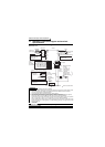
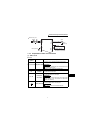
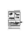
1.2 Main circuit terminals
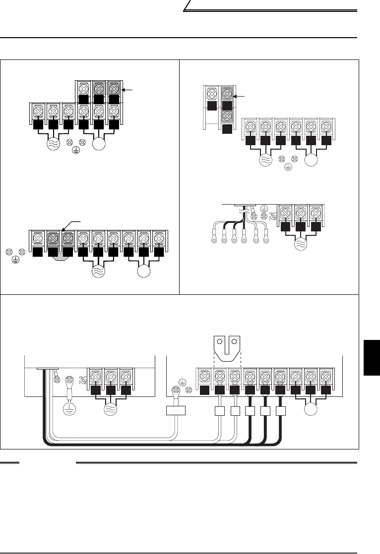
1.2.1 Terminal block layout
zFR-F520J-0.4K, 0.75K
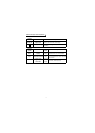
zFR-F520J-5.5K, 7.5K, 11K, 15K
zFR-F540J-5.5K, 7.5K, 11K, 15K
zFR-F520J-1.5K, 2.2K, 3.7K
z
FR-F540J-0.4K, 0.75K, 1.5K, 2.2K, 3.7K
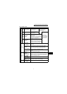
zFilter pack
FR-BFP-(H)0.4K to (H)15K
zConnection of the inverter and filter pack
(For details, refer to the instruction manual (basic).)
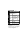
CAUTION
•Make sure the power cables are connected to the R0, S0, T0 of the filter pack (FR-
BFP) (If using the inverter without filter pack, connect to the R, S, T of the
inverter). Never connect the power cable to the U, V, W of the inverter. (Phase
need not be matched)
•Connect the motor to U, V, W. At this time, turning on the forward rotation switch
(signal) rotates the motor in the counterclockwise direction when viewed from the
motor shaft.
•When connecting the filter pack, make sure the jumper across the terminals P1-P
of the inverter is removed.
N/- P/+
P1
U V W
IM
R/L1 S/L2 T/L3
Jumpe
r
Power supply
Motor
Motor
Jumper
U V W
IM
P1
Power supply
R/L1 S/L2
P/+
N/-
T/L3
N/-
P/+
P1
Jumper
Power su
pp
l
y
Motor
R/L1 S/L2 T/L3
U V W
IM
To the inverter
terminal block
R0 S0 T0
Power
supply
RST P1PGND
Earth
(Ground)
R0 S0 T0
Power supply
Filter pack
(FR-BFP)
Inverter
(FR-F500J)
R/L1 S/L2
P1
P/+
T/L3
P1 P R S T
Motor
U V W
IM
N/-
GND
Jumper