


19
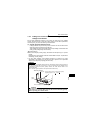
Main circuit terminals
1
WIRING
1.2.10 Power supply harmonics
The inverter may generate power supply harmonics from its converter circuit to affect
the power generator, power capacitor etc. Power supply harmonics are different from
noise and leakage currents in source, frequency band and transmission path. Take the
following countermeasure suppression techniques.
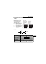
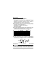
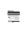
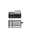
The following table indicates differences between harmonics and noise:
*The filter pack (FR-BFP) produces the same effect as when the DC reactor (FR-
HEL(-H)/FR-BEL(-H)) is connected.
Item Harmonics Noise
Frequency
Normally 40th to 50th degrees or less
(up to 3kHz or less)
High frequency (several 10kHz
to 1GHz order)
Environment To-electric channel, power impedance To-space, distance, wiring path
Quantitative
understanding
Theoretical calculation possible
Random occurrence,
quantitative grasping difficult
Generated amount Nearly proportional to load capacity
Change with current variation
ratio (larger as switching speed
increases)
Affected equipment
immunity
Specified in standard per equipment
Different depending on maker's
equipment specifications
Suppression example Provide reactor.* Increase distance.
Suppression technique
Harmonic currents produced
on the power supply side by
the inverter change with such
conditions as whether there
are wiring impedances and a
DC reactor (FR-HEL(-H)/FR-
BEL(-H) or FR-HAL(-H)/FR-
BAL(-H)) and the magnitudes
of output frequency and
output current on the load
side.
For the output frequency and output current, we understand that they should be
calculated in the conditions under the rated load at the maximum operating frequency.
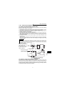
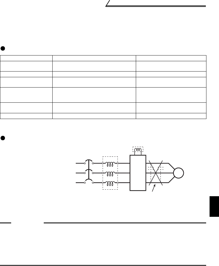
CAUTION
The power factor improving capacitor and surge suppressor on the inverter
output side may be overheated or damaged by the high frequency components
of the inverter output. Also, since an excessive current flows in the inverter to
activate overcurrent protection, do not provide a capacitor and surge
suppressor on the inverter output side when the motor is driven by the inverter.
To improve the power factor, insert a reactor on the inverter's primary side or
DC circuit. For full information, refer to page 16.
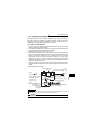
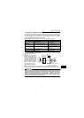
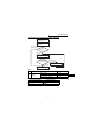
Inverter
MCCB
Do not provide power factor
improving capacitor.
Motor
IM
FR-HAL(-H)
/FR-BAL(-H)
FR-HEL(-H)
/FR-BEL(-H)