


129
Operation selection function
2
FUNCTIONS
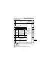
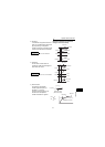
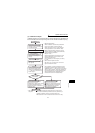
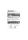
(7) Calibration example
(A detector of 4mA at 0°C and 20mA at 50°C is used to adjust the room temperature to
25°C under PID control. The set point is given to across inverter terminals 2-5 (0-5V).)
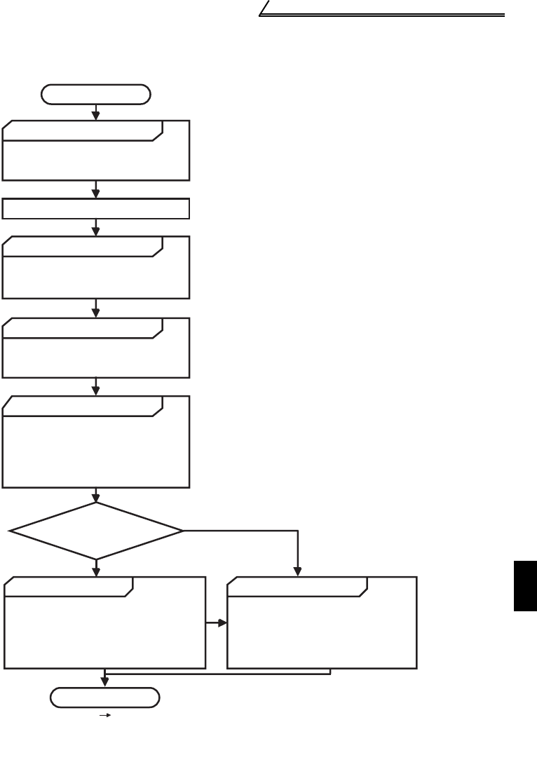
START
Is the setting
value steady?
Adjust parameters.
END
Yes
No
Set "20" or "21" in Pr. 88 and turn on the X14
signal to enable PID control.
.......
Determine the set point.
Determine the set point of the item
to be adjusted.
Convert the set point into %.
Calculate the ratio of the set point
to the detector output.
Make calibration.
Set the set point.
Enter a voltage to across
terminals 2-5 according to the set
point (%).
Operation
Set the proportional band and
integral time to slightly higher
values and the differential time to
"- - -" (No control)
, and switch on
the start signal.
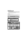
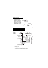
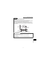
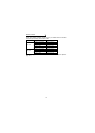
Detector specifications
.......
When the set point setting input (0 to 5V) and
detector output (4 to 20mA) must be calibrated,
make the following calibration*.
.......
.......
.......
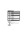
Set the proportional band and
integral time to slightly higher values
and set the differential time to a
slightly lower value to stabilize the
measured value.
Optimize parameters.
While the measured value is
steady, the proportional band and
integral time may be reduced and
the differential time increased
throughout the operation.
*When calibration
is required
Set point = 50%
Since the specifications of terminal 2 are such
that 0% is equivalent to 0V and 100% to 5V,
enter 2.5V into terminal 2.
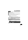
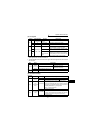
For PU operation, set the set point (0 to 100%)
in Pr. 93.
During operation, set the proportional band and
integral time to slightly higher values and set the
differential time to "- - -" (No control). In accordance
with the system operation, reduce the proportional
band and integral time. For slow response system
where a deadband exists, differential control
should be turned on and increased slowly.
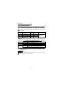
Use Pr. 38 and calibration parameters C2 to C4 (terminal 2)
and Pr. 39 and calibration parameters C5 to C7 (terminal 4) to
calibrate the detector output and set point setting input.
Make calibration in the PU mode when the inverter is at a stop.
Set the room temperature to 25°C
When the detector used has the specifications
that 0°C is equivalent to 4mA and 50°C to
20mA, the set point of 25° C is 50% because
4mA is equivalent to 0% and 20mA to 100%.