


29
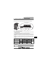
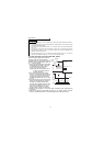
Input terminals
1
WIRING
*1: Also stopped by the . Refer to page 116.
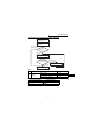
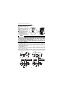
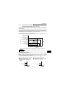
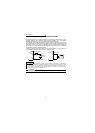
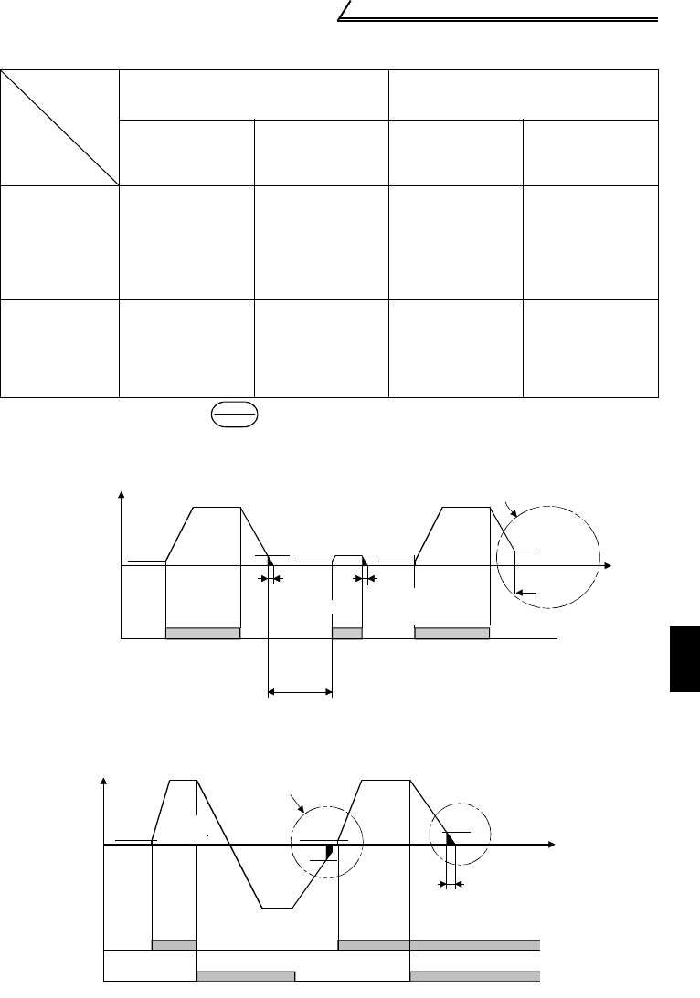
Start/Stop Timing Chart (for two-wire type)
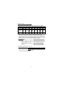
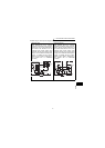
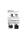
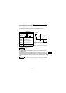
Forward-Reverse Rotation Switch-Over Timing Chart
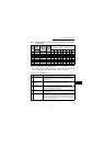
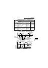
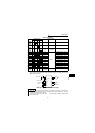
DC Injection Brake and Coasting to Stop Functionality
Operation
Mode
DC Injection
Brake
External Operation or Combined
Operation
Pr. 79 = "0", "2", "3"
PU Operation or Combined
Operation
Pr. 79 = "0", "1", "4"
Terminals STF
(STR)-SD
disconnected
(*1)
Set frequency
changed to 0Hz
Stop key
Set frequency
changed to 0Hz
DC injection
brake enabled
DC injection brake
operated at not
more than "DC
injection brake
operation
frequency" set in
Pr. 10
DC injection brake
operated at 0.5Hz
or less.
DC injection brake
operated at not
more than "DC
injection brake
operation
frequency" set in
Pr. 10
DC injection brake
operated at 0.5Hz
or less.
DC injection
brake disabled
Coasted to a stop
at not more than
"DC injection
brake operation
frequency" set in
Pr. 10
Coasted to a stop
at 0.5Hz or less.
Coasted to a stop
at not more than
"DC injection
brake operation
frequency" set in
Pr. 10
Coasted to a stop
at 0.5Hz or less.
STOP
RESET
DC injection
brake operation
time Pr. 11
Output frequency
Starting frequency
Pr.13
(*1)
0.5Hz
ON
DC injection brake
operation
frequency Pr. 10
3Hz
0.5s
DC injection
brake operation
time Pr. 11
0.5Hz
0.5s
ON
0.5Hz
ON
3Hz
Coasted to
a stop
Time
DC injection brake
not operated
DC injection brake disabledDC injection brake enabled
Start signal
terminal
(*4)
(*3)
(*3)
(*2)
Across STF-SD
Across STR-SD
Output frequency
Starting
frequency
Pr.13
(*1)
0.5Hz
Forward
rotation
Forward
rotation
3Hz
3Hz
Start signal switched on
while DC injection brake
is being operated
DC injection brake operation
frequency Pr. 10
DC injection
brake enabled
Time
DC injection brake
operation time Pr. 11
0.5s
ON
ON ON
ON
Reverse
rotation
0.5Hz
Start
signal
terminal
(*3)
(*4)
Across
STF-SD
Across
STR-SD