


2
Standard connection diagram and terminal specifications
1.1 Standard connection diagram and terminal
specifications
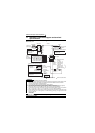
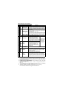
1.1.1 Standard connection diagram
zWith filter pack
REMARKS
*1. Not needed when the setting dial is used for calibration.
Used when calibration must be made near the frequency meter for such a reason as a remote frequency meter.
However, the frequency meter needle may not deflect to full-scale if the calibration resistor is connected.
In this case, use this resistor and setting dial together.
*2. You can switch the position of sink and source logic. Refer to page 26.
*3. When the setting potentiometer is used frequently, use a 2W1kΩ potentiometer.
*4. The terminal functions change with input terminal function selection (Pr. 60 to Pr. 63). (Refer to page 109.)
(RES, RL, RM, RH, RT, AU, STOP, MRS, OH, REX, JOG, X14, X16, (STR) signal selection)
*5. The terminal function changes with the setting of output terminal function selection (Pr. 64, Pr. 65). (Refer to
page 111.) (RUN, SU, OL, FU, RY, Y12, Y13, FDN, FUP, RL, Y95, LF, ABC signal selection)
*6. Connect the GND cable of the filter pack to the earth (ground) terminal of the inverter. Use the earth (ground)
terminal of the filter pack to earth (ground). For inverter earthing (grounding), earth (ground) the inverter
through the filter pack.
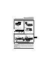
CAUTION
To prevent a malfunction due to noise, keep the signal cables more than 10cm away
from the power cables.
When using current input as the
frequency setting signal, turn the
AU signal on.
Current input selection
AU
Multi-speed
selection
3-phase AC
power supply
MCCB MC
PC
P/+
P1
N/-
External transistor common
24VDC power supply
Contact input common (source)
Take care not to short
terminals PC-SD.
Jumper: Remove this
jumper to connect
the filter pack.
POINT
R
S
T
R0
S0
T0
P1
P
Filter pack
RS-485
connector
*3
*5
*5
*5
*1
*4
*4
*4
*2
Earth
(Ground)
GND
*5
*6
Control circuit terminalMain circuit terminal
SINK
SOURCE
FM
SD
(+)
Calibration
resistor
(-)
Indicator
1mA full-scale
Analog meter
(Digital indicator)
1mA
Earth (Ground)
Control input
signals
(No voltage
input allowed)
Contact input common
SD
*4
STF
STR
RM
Forward rotation start
Reverse rotation start
Middle speed
High speed
RH
Frequency setting
potentiometer
1/2W1kΩ
Frequency setting signals (Analog)
10
2
2
3
1
4 to 20mADC(+)
4
RUN
SE
Running
Alarm output
0 to 5VDC
0 to 10VDC
Operation status
output
5
Open
collector
output
common
Current input(-)
Open
collector
outputs
(+5V)
(Common)
(4 to 20mADC)
A
B
C
Motor
IM
U
V
W
Inverter
Selected
R/L1
S/L2
T/L3