


42
Connection to the stand-alone option
1.6 Connection to the stand-alone option
The inverter accepts a variety of stand-alone option units as required.
Incorrect connection will cause inverter damage or accident. Connect and operate the
option unit carefully in accordance with the corresponding option unit manual.
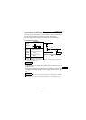
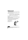
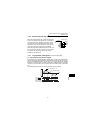
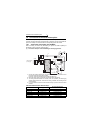
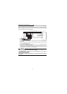
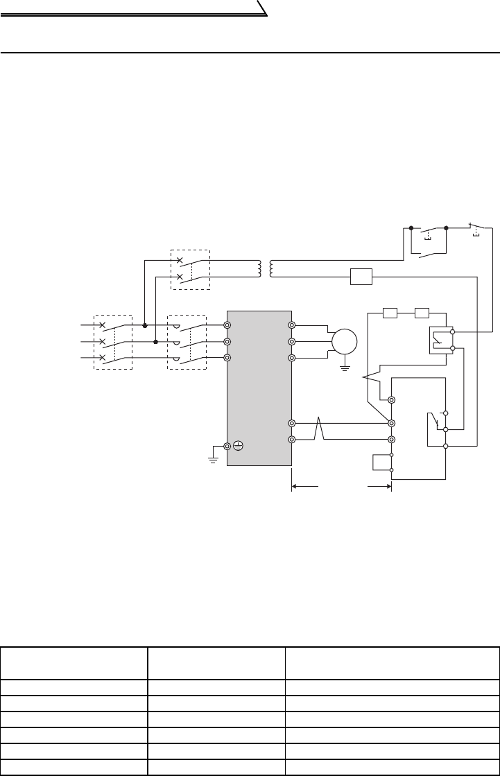
1.6.1 Connection of the brake unit (FR-BU2)
When connecting the brake unit (FR-BU2(H)) to improve the brake capability at
deceleration, make connection as shown below.
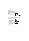
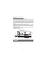
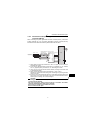
(1) Connection example with the GRZG type discharging resistor
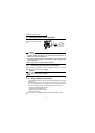
<Recommended external thermal relay>
*1. Connect the inverter terminals (P/+, N/-) and brake unit (FR-BU2) terminals so that
their terminal names match with each other.
(Incorrect connection will damage the inverter and brake unit.)
*2. When the power supply is 400V class, install a step-down transformer.
*3. The wiring distance between the inverter, brake unit (FR-BU2) and discharging
resistor should be within 5m. Even when the wiring is twisted, the cable length must
not exceed 10m.
*4. It is recommended to install an external thermal relay to prevent overheat of brake
resistors.
Brake Unit Discharging Resistor
Recommended External
Thermal Relay
FR-BU2-1.5K GZG 300W-50Ω TH-N20CXHZ 1.3A
FR-BU2-3.7K GRZG 200-10
Ω TH-N20CXHZ 3.6A
FR-BU2-7.5K GRZG 300-5
Ω TH-N20CXHZ 6.6A
FR-BU2-15K GRZG 400-2
Ω TH-N20CXHZ 1.1A
FR-BU2-H7.5K GRZG 200-10
Ω TH-N20CXHZ 3.6A
FR-BU2-H15K GRZG 300-5
Ω TH-N20CXHZ 6.6A
U
V
W
P/+
N/-
R/L1
S/L2
T/L3
Motor
IM
PR
N/-
BUE
SD
P/+
A
B
C
FR-BU2
GRZG type
discharging resistor
RR
MC
OFFON
MC
Three-phase AC
power supply
MCCB
MC
Inverter
5m or less
T
*3
*2
*1
*3
*1
*4