


192
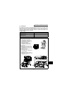
Precautions for maintenance and inspection
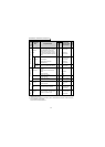
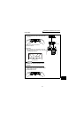
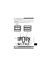
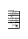
Measuring Points and Instruments
Item
Measuring
Point
Measuring
Instrument
Remarks
(Reference Measurement Value)
Power supply
voltage
V1
Across R-S,
S-T, T-R
Moving-iron
type AC voltmeter
Commercial power supply
Within permissible AC voltage
fluctuation
(Refer to page 196.)
Power supply side
current
I1
R, S, and T
line currents
Moving-iron
type AC ammeter
Power supply side
power
P1
At R, S and T,
and across R-
S, S-T and T-
R
Electrodynamic type
single-phase wattmeter
P1 = W11 + W12 + W13
(3-wattmeter method)
Power supply side
power factor
Pf1
Calculate after measuring power supply voltage, power supply side current
and power supply side power.
[Three phase power supply]
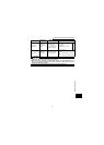
Output side
voltage
V2
Across U-V,
V-W and W-U
Rectifier type AC
voltmeter (Caution 1)
(Moving-iron type
cannot measure)
Difference between the phases is
within
±1% of the maximum output
voltage.
Output side
current
I2
U, V and W
line currents
Moving-iron type AC
ammeter
(Caution 2)
Current should be equal to or less
than rated inverter current.
Difference between the phases is
10% or lower of the rated inverter
current.
Output side power
P2
U, V, W and
U-V, V-W
Electrodynamic type
single-phase wattmeter
P2 = W21 + W22
2-wattmeter method
(or 3-wattmeter method)
Output side power
factor
Pf2
Calculate in similar manner to power supply side power factor.
Converter output Across P-N
Moving-coil type
(such as tester)
Inverter LED display is lit
1.35
× V1
Frequency
setting signal
Across 2(+)-5
Moving-coil type
(Tester and such may
be used)
(Internal resistance:
50kΩ or larger)
0 to 5VDC/0 to 10VDC
"5" is common
Across 4(+)-5 4 to 20mADC
Frequency setting
power supply
Across 10(+)-5 5VDC
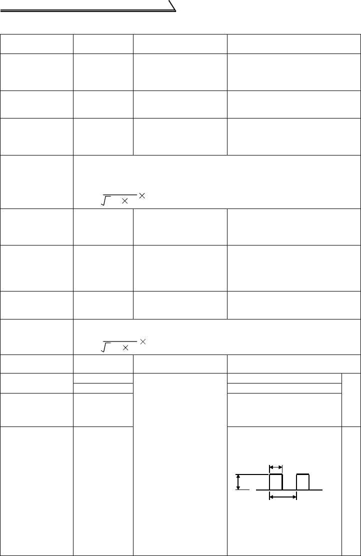
Frequency meter
signal
Across
FM(+)-SD
Approx. 5VDC at maximum
frequency
(without frequency meter)
Pulse width T1: Adjust with
C1
Pulse cycle T2: Set with
Pr. 55 (Pr.
56)
"SD" is common
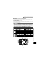
Pf1=
P1
3V1 I1
100%
Pf2=
P2
3V2 I2
100%
8VDC
T1
T2