


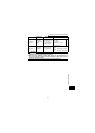
197
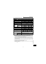
Specification list
4
SPECIFICATIONS
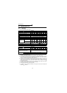
(2) Three-phase 400V power supply
*1. The applicable motor capacity indicated is the maximum capacity applicable for use of the
Mitsubishi 4-pole standard motor.
*2. The rated output capacity indicated assumes that the output voltage is 440V.
*3. The % value of the overload current rating indicated is the ratio of the overload current to
the inverter's rated output current. For repeated duty, allow time for the inverter and motor
to return to or below the temperatures under 100% load.
*4. The maximum output voltage does not exceed the power supply voltage. You can set the
maximum output voltage to any value below the power supply voltage. However, the
pulse voltage value of the inverter output side voltage remains unchanged at about
that of the power supply.
*5. The power supply capacity varies with the value of the power supply side inverter
impedance (including those of the input reactor and cables).
*6. The inverter with filter pack is open type (IP00).
*7. The leakage current indicated is equivalent to one-phase of cable for the three-phase
three wire connection.
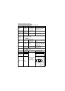
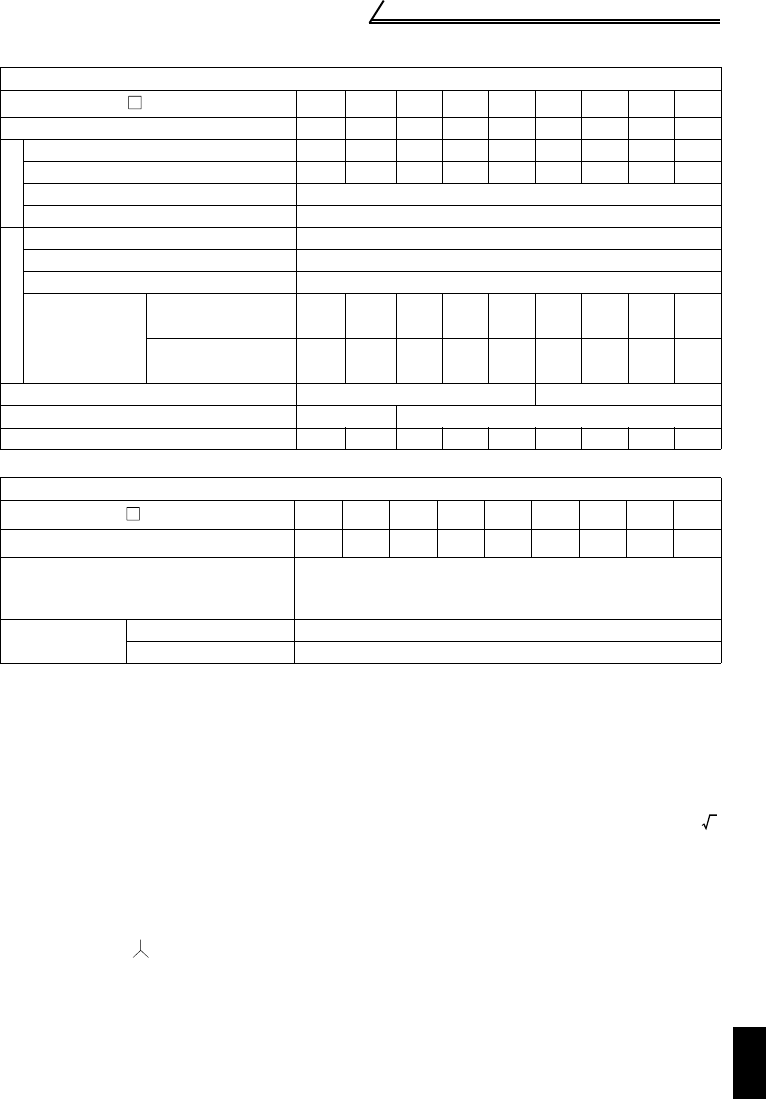
Inverter
Type FR-F540J- K
0.4 0.75 1.5 2.2 3.7 5.5 7.5 11 15
Applicable motor capacity (kW) (*1) 0.4 0.75 1.5 2.2 3.7 5.5 7.5 11 15
Output
Rated capacity (kVA) (*2) 0.9 1.6 2.8 3.7 6.2 9.1 12.4 17.5 22.5
Rated current (A) 1.1 2.1 3.7 4.8 8.1 12 16.3 23 29.5
Overload current rating (*3) 120% 60s, 150% 0.5s (inverse time characteristics)
Voltage (*4) Three-phase 380 to 480V
Power supply
Rated input AC voltage/frequency Three-phase 380 to 480V 50Hz/60Hz
Permissible AC voltage fluctuation 325 to 528V 50Hz/60Hz
Permissible frequency fluctuation Within ±5%
Power supply
system
capacity (kVA)
(*5)
Without filter pack 1.1 2.2 4.2 4.8 8.6 12 17 20 28
With filter pack 0.7 1.3 2.7 3.3 5.4 8.5 11 16 19
Protective structure (JEM1030) Enclosed type (IP20) (*6) Open type (IP00)
Cooling system Self-cooling Forced air cooling
Approximate mass (kg) 1.5 1.5 1.5 1.6 1.7 3.8 3.8 5.0 7.5
Filter pack
Type FR-BFP-H K
0.4 0.75 1.5 2.2 3.7 5.5 7.5 11 15
Approximate mass (kg) 1.6 1.7 1.9 2.3 2.6 4.5 5.0 7.0 8.2
Power factor improving reactor
Install the DC reactor on the DC side.
(93% to 95% of power supply power factor under 100%
load)
Noise filter
Common mode core Install a ferrite core on the input side
Capacitive filter About 8mA of capacitor leakage current (*7)
2