


28
Input terminals
1.4 Input terminals
1.4.1 Run (start) and stop (STF, STR, STOP)
To start and stop the motor, first switch on the input power supply of the inverter to turn
on the magnetic contactor at the operation-ready when there is a magnetic contactor
on the input side, then start the motor with the forward or reverse rotation start signal.
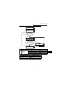
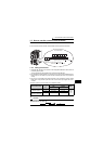
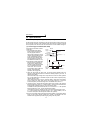
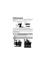
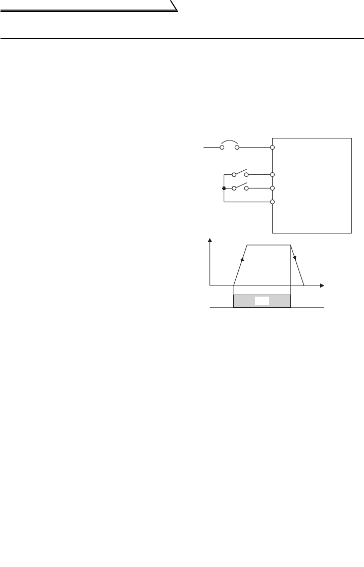
(1) Two-wire type connection (STF, STR)
A two-wire type connection is shown
on the right.
1) The forward/reverse rotation
signal is used as both the start
and stop signals. Switch on
either of the forward and reverse
rotation signals to start the motor
in the corresponding direction.
Switch on both or switch off the
start signal during operation to
decelerate the inverter to a stop.
2) The frequency setting signal may
either be given by entering 0 to
5VDC (or 0 to 10VDC) across
frequency setting input terminals
2-5 or by setting the required
values in Pr. 4 to Pr. 6 "multi-
speed setting" (high, middle, low
speeds). (For multi-speed
operation, refer to page 32.)
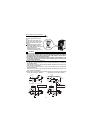
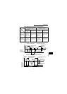
3) After the start signal has been input, the inverter starts operating when the
frequency setting signal reaches or exceeds the "starting frequency" set in Pr. 13
(factory-set to 0.5Hz).
If the motor load torque is large or the "torque boost" set in Pr. 0 is small, operation
may not be started due to insufficient torque until the inverter output frequency
reaches about 3 to 6Hz.
If the "minimum frequency" set in Pr. 2 (factory setting = 0Hz) is 6Hz, for example,
merely entering the start signal causes the running frequency to reach the
minimum frequency of 6Hz according to the "acceleration time" set in Pr. 7.
4) To stop the motor, operate the DC injection brake for the period of "DC injection
brake operation time" set in Pr. 11 (factory setting = 0.5s) at not more than the DC
injection brake operation frequency or at not more than 0.5Hz.
To disable the DC injection brake function, set 0 in either of Pr. 11 "DC injection
brake operation time" or Pr. 12 "DC injection brake voltage".
In this case, the motor is coasted to a stop at not more than the frequency set in
Pr. 10 "DC injection brake operation frequency" (0 to 120Hz variable) or at not
more than 0.5Hz (when the DC injection brake is not operated).
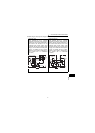
5) If the reverse rotation signal is input during forward rotation or the forward rotation
signal is input during reverse rotation, the inverter is decelerated and then
switched to the opposite output without going through the stop mode.
ON
MCCB
Power
supply
Forward
rotation start
Reverse
rotation start
STF
STR (Pr.63= "- - -" )
Inverter
Output frequency
Time
2-wire type connection example
SD
R, S, T
Across
STF-SD
(STR)