177
Errors (Alarms)
3
PROTECTIVE FUNCTIONS
3.1.2 To know the operating status at the occurrence of alarm
(only when FR-PU04 is used)
When any alarm has occurred, the display automatically switches to the indication of the
corresponding protective function (error). By pressing the at this point without
resetting the inverter, the display shows the output frequency. In this way, it is possible to
know the running frequency at the occurrence of the alarm. It is also possible to know
the current in the same manner. After resetting, you can confirm the definitions in "Alarm
History". (For details, refer to the instruction manual of the parameter unit (FR-PU04).)
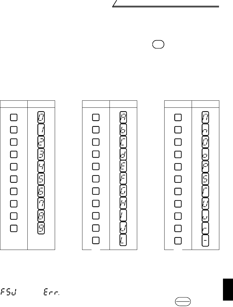
3.1.3 Correspondence between digital and actual characters
There are the following correspondences between the actual alphanumeric characters
and the digital characters displayed on the operation panel:
3.1.4 Resetting the inverter
The inverter can be reset by performing any of the following operations. Note that the
internal thermal integrated value of the electronic thermal relay function and the
number of retries are cleared (erased) by resetting the inverter.
Recover about 1s after reset is cancelled.
(F5J) and (Err) appears alternately on the operation panel during reset.
Operation 1 ....... Using the operation panel, perform a reset with the .
(Enabled only when the inverter protective function is activated
(major failure))
Operation 2........ Switch power off once, then switch it on again after the LED on the
operation panel turns off.
Operation 3 ....... Turn on the reset signal (RES). (Assign this signal using any of Pr.
60 to Pr. 63.) (Refer to page 40, 109.)
Actual Display Actual Display Actual Display
MON
0
1
2
3
4
5
6
7
8
9
A
B
C
D
E
F
G
H
I
J
L
M
N
O
P
T
U
V
r
-
S
o
STOP
RESET


