134
Maintenance function
2.11.3 Motor primary resistance (Pr. 99 )
2.12 Maintenance function
2.12.1 Maintenance output function (H1 , H2
)
The parameter numbers in parentheses are those for use with the parameter unit (FR-
PU04).
<Setting>
Generally this parameter need not be set. At the factory setting of "- - -", the
standard motor constant of the motor capacity set in Pr. 98 (including that of the
constant-torque motor) is used.
Parameter Name
Factory
Setting
Setting
Range
Remarks
99
Motor primary
resistance
- - -
0 to 50
Ω,
- - -
Setting is enabled when Pr. 30 = "1"
♦Related parameters♦
• Applied motor setting ⇒ Pr. 71 "applied motor" (refer to page 80)
• Automatic torque boost selection ⇒ Pr. 98 "automatic torque boost selection (motor capacity)"
(refer to page 133)
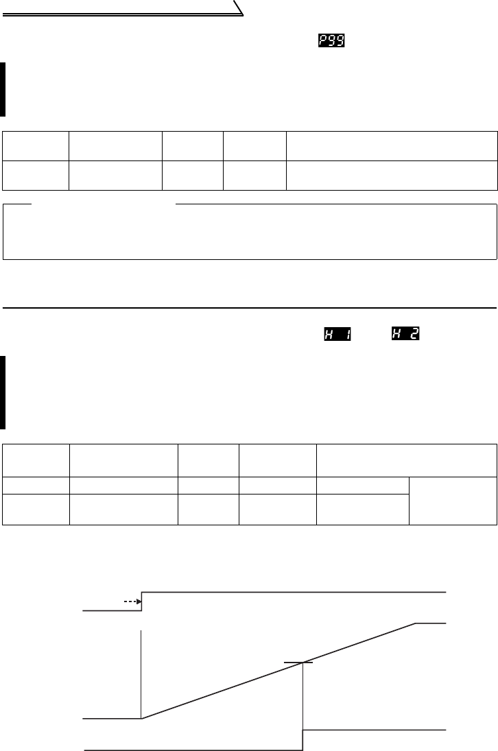
The maintenance timer alarm signal (Y95) is output when the cumulative
energization time (H1 "maintenance timer") of the inverter reaches the time set
in H2 "maintenance alarm output set time". (Used to alert the operator of the
main circuit smoothing capacitor life expiration, for example.)
Parameter Name
Factory
Setting
Setting
Range
Remarks
H1 (503) Maintenance timer 0 0 to 999 Write disabled
Setting is
enabled when
Pr. 30 = "1"
H2 (504)
Maintenance alarm
output set time
87
(87000h)
0 to 999, - - -
- - -: Function as
87000h
Initial power-on
Maintenance timer
H1(Pr.503)
Y95 output/indication
OFF ON
H2(Pr. 504)
999000h


