


46
Connection to the stand-alone option
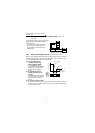
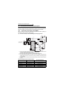
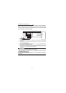
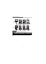
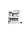
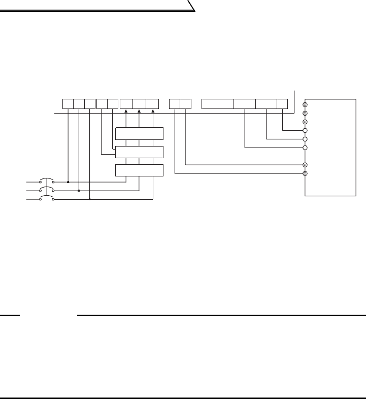
1.6.4 Connection of the high power factor converter (FR-HC)
When connecting the high power factor converter (FR-HC) to suppress power supply
harmonics, perform wiring securely as shown below. Incorrect connection will damage
the high power factor converter and inverter.
*1. The power input terminals R, S, T must be open. Incorrect connection will damage
the inverter.
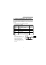
*2. Use Pr. 60 to Pr. 63 (input terminal function selection) to assign the terminals used
for the RES and MRS signals.
*3. Do not insert MCCB between terminals P-N (P - P, N - N). Opposite polarity of
terminals N, P will damage the inverter.
*4. Be sure to connect terminal RDY of the FR-HC to the MRS signal assigned terminal
of the inverter, and connect terminal SE of the FR-HC to terminal SD of the inverter.
Without proper connecting, FR-HC will be damaged.
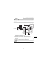
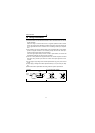
CAUTION
•Use sink logic (factory setting) when the FR-HC is connected. The FR-HC
cannot be connected when source logic is selected.
•The voltage phases of terminals R, S, T and terminals R4, S4, T4 must be
matched before connection.
•Do not connect the filter pack.
•Do not remove a jumper across terminal P and P1 except when connecting a
DC reactor.
From FR-HCL02
Power
supply
MCCB
R
S
TR4
S4
T4 N
P
Y1 or Y2 RDY RSO SE
High power factor converter (FR-HC)
Inverter
MRS *2
RES *2
SD
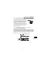
External box
FR-HCL01
R4
S4
T4
R3
S3
T3
R2
S2
T2
R
S
T
MC2
MC1
MC1MC2
*1
*4
N/-
P/+ *3
T/L3
S/L2
R/L1