


6
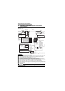
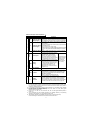
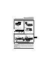
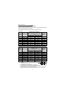
Standard connection diagram and terminal specifications
*1. Do not connect terminals SD and PC each other or to the earth (ground).
For sink logic (factory setting), terminal SD acts as the common terminal of contact input.
For source logic, terminal PC acts as the common terminal of contact input. (Refer to
page 26 for switching method.)
*2. Low indicates that the open collector output transistor is on (conducts). High indicates
that the transistor is off (does not conduct).
*3. RL, RM, RH, RT, AU, STOP, MRS, OH, REX, JOG, RES, X14, X16, (STR) signal
selection (Refer to page 109.)
*4. RUN, SU, OL, FU, RY, Y12, Y13, FDN, FUP, RL, Y95, LF, ABC signal selection (Refer to
page 111.)
*5. To be compliant with the European Directive (Low Voltage Directive), the operating
capacity of relay outputs (A, B, C) should be 30VDC 0.3A.
*6. Terminals SD, SE and 5 are isolated from each other. Do not earth (ground).
Avoid connecting the terminal SD and 5 and the terminal SE and 5.
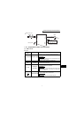
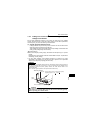
Input signals
Frequency setting
2
Frequency setting
(voltage signal)
Inputting 0 to 5VDC (or 0 to 10V) provides the maximum output
frequency at 5V (10V) and makes input and output proportional.
Switch between 5V and 10V using Pr. 73 "0-5V, 0-10V selection".
Input resistance 10kΩ. Maximum permissible input voltage 20V
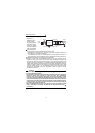
4
Frequency setting
(current signal)
Input 4 to 20mADC. It is factory set at 0Hz for 4mA and at
60Hz for 20mA.
Maximum permissible input current 30mA. Input resistance
approximately 250Ω.
Turn ON signal AU for current input.
Turning the AU signal on makes voltage input invalid. Use any of
Pr. 60 to Pr. 63 (input terminal function selection) to set the AU
signal.
5
Frequency setting
input common
Frequency setting signal (terminal 2, 4) common terminal.
Do not earth (ground).
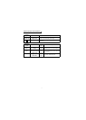
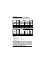
Output signals
A
B
C
Alarm output
1 changeover contact output indicates
that the inverter protective function has
activated and the output stopped.
230VAC 0.3A, 30VDC 0.3A. Alarm:
discontinuity across B-C (continuity
across A-C), Normal: continuity across
B-C (discontinuity across A-C).(*5)
The function of the
terminals changes
according to the
output terminal
function selection
(Pr. 64, Pr.65).
(*4)
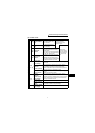
Open collector
RUN
Inverter
running
Switched low when the inverter output
frequency is equal to or higher than the
starting frequency (factory set to 0.5Hz
variable). Switched high during stop or
DC injection brake operation. (*2)
Permissible load 24VDC 0.1A (a
voltage drop is 3.4V maximum when
the signal is on)
SE
Open collector
common
Common terminal for inverter running terminal RUN.
(*6)
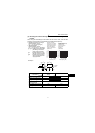
Indicator
FM For meter
The output signal across terminals FM-SD is factory set to about
1mA at 60Hz and is proportional to the corresponding output
frequency. Since output voltage is pulse waveform, a digital
meter can be connected.
Frequency permissible load current 1mA
Pulse specification 1440 pulses/s at 60Hz
Communication
——
RS-485
connector
Using the parameter unit connection cable (FR-CB201 to
205), the parameter unit (FR-PU04) can be connected.
Communication operation can be performed using RS-485.
For details of RS-485 communication, refer to page 48.
Symbol Terminal Name Definition