


35
Input terminals
1
WIRING
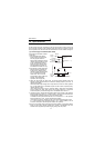
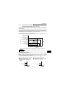
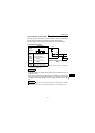
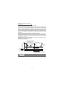
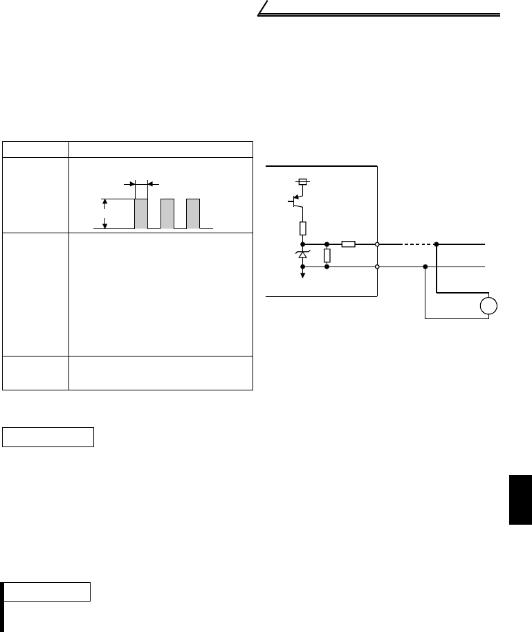
Output waveform of terminal FM
The output signal of terminal FM has a pulse waveform as shown in the table below
and the number of its pulses is proportional to the inverter output frequency.
The output voltage (average voltage) is also proportional to the output frequency.
Terminal FM Output Voltage
*1. 0.5V or less when a DC ammeter of 300Ω or less internal resistance is connected to
measure the output voltage.
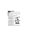
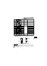
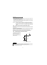
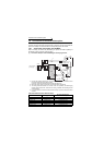
• Analog meter
To adjust the reading of an analog indicator (ammeter), turn the calibration resistor to
change the current.
When using the operation panel or parameter unit for adjustment, change the pulse
width of the output waveform (calibration parameter "C1") (adjust the current through
the adjustment of the output voltage) to adjust the reading. (For details, refer to page
137.)
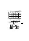
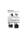
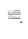
Specifications
Example of Inverter and Frequency
Meter
Output
waveform
Number of
output
pulses
(pulses/
second)
Max. 2400 pulses/s
Set a full-scale value which
achieves 1440 pulses/s.
Pr. 55: frequency monitoring
reference
Pr. 56: current monitoring
reference
Output
voltage
0 to 8VDC max. (*1)
(Approx. 5V at 1440 pulses/s)
Adjustment
REMARKS
It is not recommended to use a voltage type indicator because it is easily affected by a voltage
drop, induction noise, etc. and may not provide correct reading if the wiring distance is long.
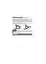
Inverter
24V
SD
FM
FM
Calibration parameter C1 (Pr. 900)
8V