


31
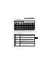
Input terminals
1
WIRING
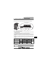
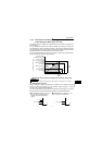
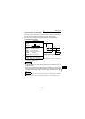
1.4.2 Connection of frequency setting potentiometer and
output frequency meter (10, 2, 5, 4, AU)
The analog frequency setting input signals that may be entered are voltage and
current signals.
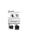
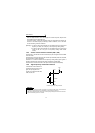
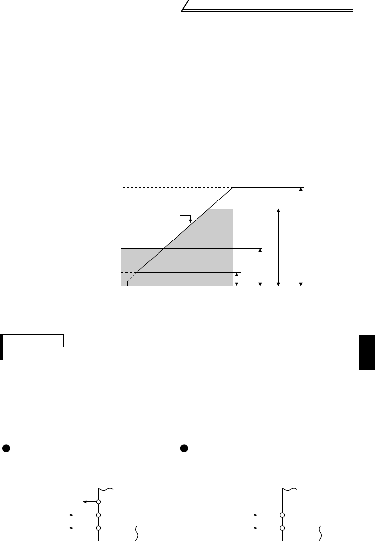
For the relationships between the frequency setting input voltages (currents) and
output frequencies, refer to the following diagram. The frequency setting input signals
are proportional to the output frequencies. Note that when the input signal is less than
the starting frequency, the output frequency of the inverter is 0Hz.
If the input signal of 5VDC (or 10V, 20mA) or higher is entered, the output frequency
does not exceed the maximum output frequency.
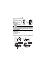
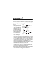
Relationships between Frequency Setting Inputs and Output Frequencies
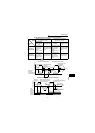
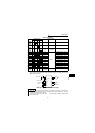
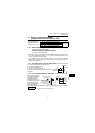
(1) Voltage input (10, 2, 5)
Enter the frequency setting input signal of 0 to 5VDC (or 0 to 10VDC) across the
frequency setting input terminals 2-5. The maximum output frequency is reached
when 5V (10V) is input across terminals 2-5.
The power supply used may either be the inverter's built-in power supply or an external
power supply. For the built-in power supply, terminals 10-5 provide 5VDC output.
REMARKS
For the way to calibrate the output frequency meter, refer to the instruction manual (basic).
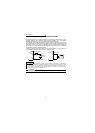
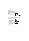
For operation at 0 to 5VDC, set "0" in
Pr. 73 to the 0 to 5VDC input. Use
terminal 10 for the built-in power
supply.
For operation at 0 to 10VDC, set "1" in
Pr. 73 to the 0 to 10VDC input.
Maximum frequency
(0 to 120Hz)
Minimum frequency
(0 to 120Hz)
Starting frequency
(0 to 60Hz)
0.5
0
Output frequencies
(Hz)
Input voltage is
proportional to
output
frequency.
Pr.38
Pr.39
Pr.1
Pr.2
Pr.13
Pr.73
5V
(10V)
(20mA)
Frequency setting signal
Frequency setting
voltage gain frequency
Frequency setting
current gain frequency
(1 to 120Hz)
+5V 10
2
5
0 to 5VDC
0 to 10VDC
2
5