


34
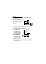
Input terminals
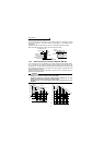
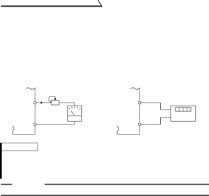
1.4.4 Indicator connection and adjustment (FM)
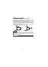
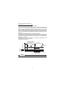
The output frequency, etc. of the inverter can be indicated by a DC ammeter of 1mA
full-scale deflection and maximum 300Ω internal resistance or a commercially
available digital indicator which is connected across terminals FM-SD.
The indicator can be calibrated from the operation panel or parameter unit. Note that
the reading varies according to the wiring distance if the indicator is placed away from
the inverter. In this case, connect a calibration resistor in series with the indicator as
shown below and adjust until the reading matches the operation panel or parameter
unit indication (indicator monitoring mode).
Install the indicator within 200m (50m for the digital indicator) of the inverter and
connect them by at least 0.3mm
2
twisted or shielded cables.
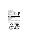
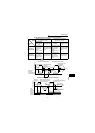
Types of Indicators Connected
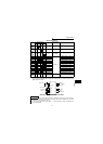
REMARKS
* Not needed when calibration is made using the calibration parameter C1 "FM terminal
calibration". This resistor is used when calibration must be made near the frequency meter
for such a reason as a remote frequency meter. Note that the needle of the frequency meter
may not deflect to full-scale when the calibration resistor is connected. In this case, use both
the resistor and calibration parameter "C1".
CAUTION
•Refer to page 137 for the procedure of indicator adjustment.
Digital indicato
r
1440 pulses/s
FM
SD
Inverter
Analog
indicator
Calibration resistor*
(+)
(1mA full-scale)
FM
SD
1mA
Inverter
(-)