


43
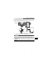
Connection to the stand-alone option
1
WIRING
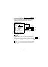
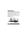
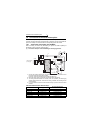
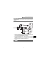
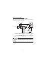
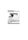
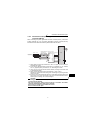
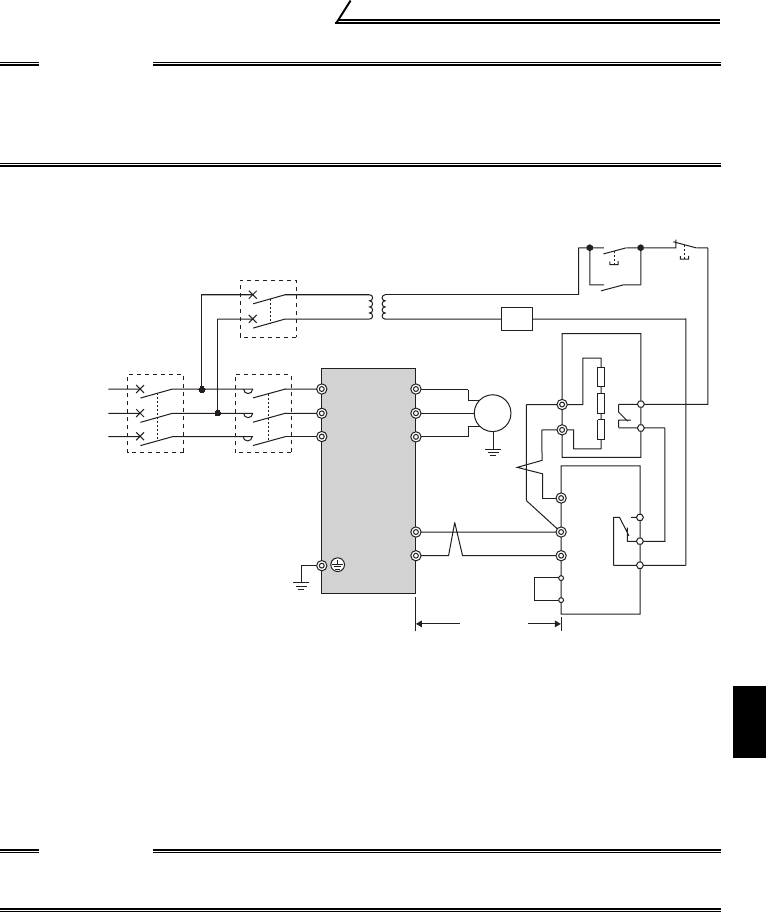
(2) Connection example with the FR-BR(-H) type resistor
CAUTION
•Set "1" in Pr. 0 "Brake mode selection" of the FR-BU2 to use GRZG type
discharging resistor.
•Do not remove a jumper across terminal P/+ and P1 except when connecting a
DC reactor.
*1. Connect the inverter terminals (P/+, N/-) and brake unit (FR-BU2) terminals so that
their terminal names match with each other.
(Incorrect connection will damage the inverter and brake unit.)
*2. When the power supply is 400V class, install a step-down transformer.
*3. The wiring distance between the inverter, brake unit (FR-BU2) and resistor unit (FR-
BR) should be within 5m. Even when the wiring is twisted, the cable length must not
exceed 10m.
*4. Normal: across TH1-TH2...close, Alarm: across TH1-TH2...open
*5. A jumper is connected across BUE and SD in the initial status.
CAUTION
•Do not remove a jumper across terminal P/+ and P1 except when connecting a
DC reactor.
U
V
W
P/+
N/-
R/L1
S/L2
T/L3
Motor
IM
PR
N/-
BUE
SD
P/+
P
A
B
C
FR-BU2
FR-BR
TH2
TH1
PR
MCCB MC
MC
OFFON
MC
T
hree-phase AC
p
ower supply
Inverter
5m or less
T
*1
*1
*2
*3
*3
*5
*4