


3
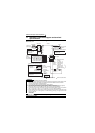
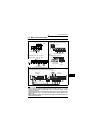
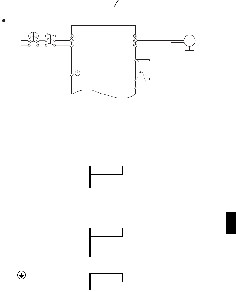
Standard connection diagram and terminal specifications
1
WIRING
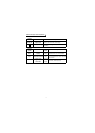
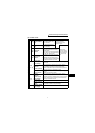
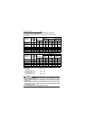
1.1.2 Explanation of main circuit terminals
(1) Main circuit
zInverter
Terminal
Symbol
Terminal Name Description
R/L1, S/L2, T/L3 AC power input
Connect the R, S, T cables of the filter pack to these
terminals.
U, V, W Inverter output
Connect to a three-phase squirrel-cage motor.
N/-
DC voltage
common
DC voltage common terminal. This is not insulated from
the power and inverter output.
P/+, P1
Filter pack
connection
Remove the jumper across terminals P-P1 and connect
the P and P1 cables of the filter pack.
Earth (Ground)
For earthing (grounding) the inverter chassis.
Connect the GND cable of the filter pack.
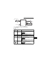
MCCB
R/L1
S/L2
Motor
IM
Earth
(Ground)
U
V
W
MC
Without filter pack
T/L3
DC reactor
(FR-HEL/BEL: option)
Jumper: Remove
this jumper when
DC reactor is connected.
P1
P/+
N/-
Earth (Ground)
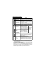
REMARKS
For the inverter without filter pack, connect these to the
commercial power supply.
REMARKS
For the inverter without filter pack, remove the jumper
across terminals P-P1 and connect the optional DC
reactor (FR-HEL/BEL).
REMARKS
Earth (Ground) the inverter without filter pack.