


45
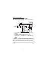
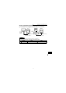
Connection to the stand-alone option
1
WIRING
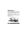
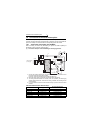
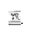
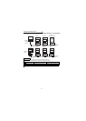
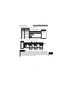
1.6.3 Connection of the brake unit (BU type)
Connect the brake unit (BU type) correctly as shown below. Incorrect connection will
damage the inverter. Remove the jumper across terminals HB-PC and terminals TB-
HC of the brake unit and fit it to across terminals PC-TB.
*1. When the power supply is 400V class, install a step-down transformer.
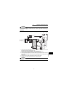
CAUTION
•The wiring distance between the inverter, brake unit and resistor unit should
be within 2m. If twisted wires are used, the distance should be within 5m.
•If the transistors in the brake unit should become faulty, the resistor can be
unusually hot, causing a fire. Therefore, install a magnetic contactor on the
inverter's power supply side to configure a circuit so that a current is shut off
in case of fault.
•Do not remove a jumper across terminal P/+ and P1 except when connecting a
DC reactor.
U
V
W
IM
HCHBHA TB
P
OCR
PR
PC
OCR
N
R/L1
S/L2
T/L3
N/−
P/+
MC
MC
OFF
ONMC
Fit a jumper
Remove the
jumper
Electrical-discharge
resistor
Brake unit (BU type)
Motor
Inverter
Three-phase AC
power supply
MCCB
T *
1