92
Explanation of functions (parameters)
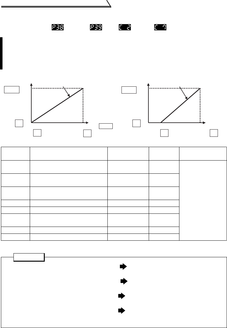
2.3.18 Biases and gains of the frequency setting voltage (current)
(Pr. 38 , Pr. 39 , C2 to C7 )
*1.Factory settings may differ because of calibration parameters.
*2.The parameter number in parentheses is the one for use with the parameter unit (FR-PU04).
You can set the magnitude (slope) of the output frequency as desired in relation
to the external frequency setting signal (0 to 5V, 0 to 10V or 4 to 20mADC).
The "bias" and "gain" functions are used to adjust the relationship between the
input signal entered from outside the inverter to set the output frequency, e.g. 0
to 5V, 0 to 10V or 4 to 20mADC, and the output frequency.
Parameter Name Factory Setting
Setting
Range
Remarks
38
Frequency setting voltage gain
frequency
60Hz 1 to 120Hz
Setting is enabled
when Pr. 30 = "1".
39
Frequency setting current gain
frequency
60Hz 1 to 120Hz
C2 (902) *2
Frequency setting voltage bias
frequency
0Hz 0 to 60Hz
C3 (902) *2 Frequency setting voltage bias 0% *1 0 to 300%
C4 (903) *2 Frequency setting voltage gain 96% *1 0 to 300%
C5 (904) *2
Frequency setting current bias
frequency
0Hz 0 to 60Hz
C6 (904) *2 Frequency setting current bias 20% *1 0 to 300%
C7 (905) *2 Frequency setting current gain 100% *1 0 to 300%
POINT
•Bias setting for 0-5VDC (0-10VDC) input Use calibration parameters C2, C3
for setting.
•Gain setting for 0-5VDC (0-10VDC) input Use Pr. 38, calibration parameter
C4 for setting.
•Bias setting for 4-20mADC input Use calibration parameters C5, C6
for setting.
•Gain setting for 4-20mADC input Use Pr. 39, calibration parameter
C7 for setting.
(For 4 to 20mADC input, turn on the AU signal.)
Frequency setting voltage signal
Factory setting
0Hz( )
C2
5V or 10V
(96% C4 *1)
0V
Pr.73
Output
frequency (Hz)
( Pr.38 )
Frequency setting current signal
20mA
4mA
Factory setting
( Pr.39 )
Output
frequency (Hz)
0Hz( )
C5
(0% C3 *1)
(Across
terminals
2-5)
(20% C6 *1)
(100% C7 *1)
(Across
terminals
4-5)
60Hz 60Hz


