


25
How to use the control circuit terminals
1
WIRING
1.3 How to use the control circuit terminals
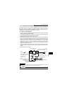
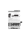
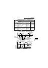
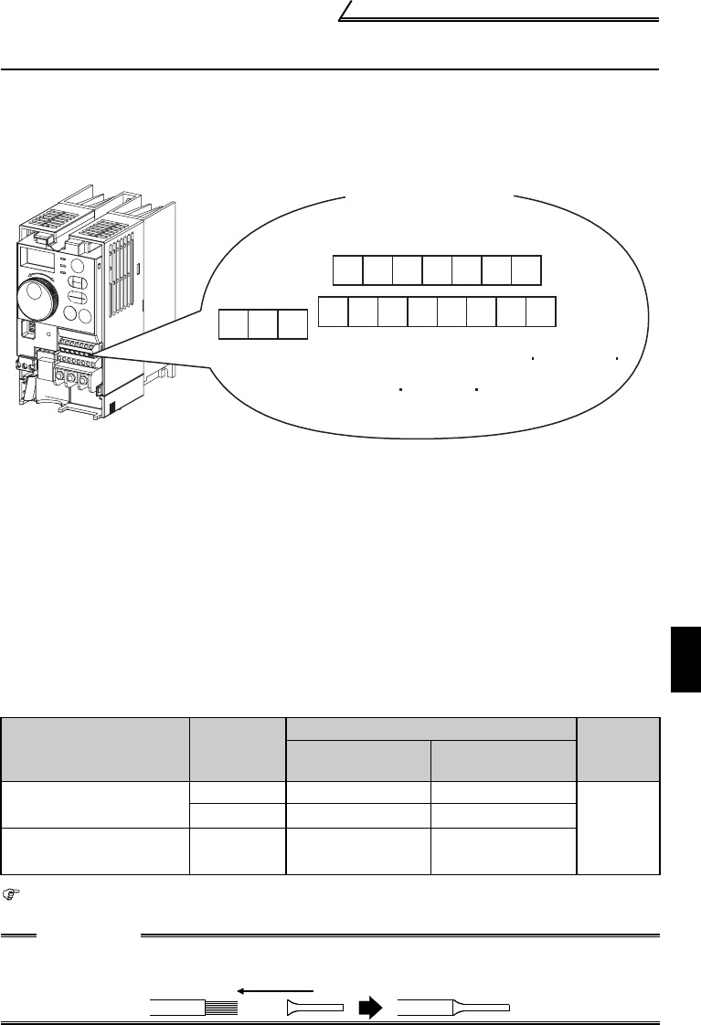
1.3.1 Terminal block layout
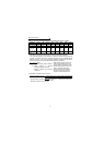
In the control circuit of the inverter, the terminals are arranged as shown below:
1.3.2 Wiring instructions
1) Terminals SD, SE and 5 are common to the I/O signals isolated from each other. Do
not earth (ground) them.
Avoid connecting the terminal SD and 5 and the terminal SE and 5.
2) Use shielded or twisted cables for connection to the control circuit terminals and run
them away from the main and power circuits (including the 200V relay sequence
circuit).
3) Use two or more parallel micro-signal contacts or twin contacts to prevent contact
faults when using contact inputs since the control circuit input signals are micro-
currents.
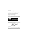
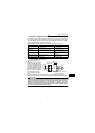
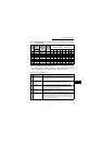
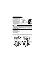
*Introduced products on bar terminals: (as of September, 2006)
Bar terminal crimping terminal: CRIMPFOX ZA3 (Phoenix Contact Co., Ltd.)
Terminal Screw Size
Wire Size
(mm
2
)
Bar Terminal Model
Maker
With
Insulation Sleeve
Without
Insulation Sleeve
M3
(terminal A, B, C)
0.3 to 0.5 Al 0,5-6WH A 0,5-6
Phoenix
Contact
Co.,Ltd.
0.5 to 0.75 Al 0,75-6GY A 0,75-6
M2
(other than the above)
0.3 to 0.5 Al 0,5-6WH A 0,5-6
CAUTION
When using the bar terminal (without insulation sleeve), use care so that the
twisted wires do not come out.
AU
FM
10 2 5 4
RM RH
Terminal arrangement
of control circuit
RUN
STR
PC SE
SD SD STF
Terminal screw
size: M3
A BC
Terminal screw size: M2
Tightening torque: 0.22N m to 0.25N m
Tightening torque: 0.5N m to 0.6N m
Wire size: 0.3mm
2
to 0.75mm
2