


17
Main circuit terminals
1
WIRING
1.2.8
Regarding noise (EMI) and the installation of a noise filter
Some noise enters the inverter causing it to malfunction and others are generated by
the inverter causing the malfunction of peripheral devices. Though the inverter is
designed to have high immunity performance, it handles low-level signals, so it
requires the following general countermeasures to be taken.
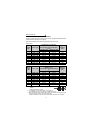
(1) General countermeasures
• Do not run the power cables (I/O cables) and signal cables of the inverter in parallel
with each other and do not bundle them.
• Use twisted shield cables for the detector connecting and control signal cables and
connect the sheathes of the shield cables to terminal SD.
• Earth (Ground) the inverter, motor, etc. at one point.
• Capacitances exist between the inverter's I/O wiring, other cables, earth (ground)
and motor, through which leakage currents flow to cause the earth leakage circuit
breaker, earth (ground) leakage relay and external thermal relay to operate
unnecessarily. To prevent this, take appropriate measures, e.g. set the carrier
frequency in Pr. 72 to a low value, use an earth (ground) leakage circuit breaker
designed for suppression of harmonics and surges, and use the electronic thermal
relay function built in the inverter.
• The input and output of the inverter main circuit include high-degree harmonics,
which may disturb communication devices (AM radios) and sensors used near the
inverter.
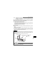
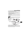
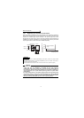
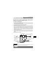
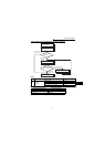
<Noise (EMI) reduction examples>
REMARKS
For the inverter without filter pack, install a line noise filter (FR-BLF, FR-BSF01) or radio noise
filter (FR-BIF) on the inverter input side as a noise reduction measure.
CAUTION
For compliance with the EU, EMC directive, please refer the instruction manual (basic).
Power
supply
for sensor
Inverter
power supply
Control
power supply
Enclosure
Reduce carrier
frequency.
IM
FR-
BLF
FR-BLF
FR-BSF01
Sensor
Use twisted pair shielded cable.
Motor
Install a line noise filter
on inverter's output side.
Inverter
Do not earth (ground)
enclosure directly.
Do not earth (ground)
control cable.
Use 4-core cable for motor
power cable and use one
cable as earth (ground) cable.
Do not earth (ground) shield but connect
it to signal common cable.
Filter
pack
Separate inverter and power
line by more than 30cm
and at least 10cm
from sensor circuit.