


185
Precautions for maintenance and inspection
3
PROTECTIVE FUNCTIONS
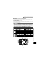
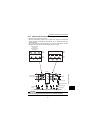
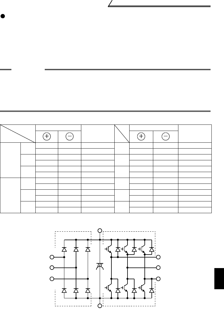
Checking the inverter and converter module
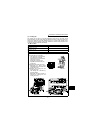
<Preparation>
(1) Disconnect the external power supply cables (R, S, T) and motor cables (U, V, W).
(2) Prepare a tester. (Use 100
Ω range).
<Checking method>
Change the polarity of the tester alternately at the inverter terminals R, S, T, U, V, W, P
and N, and check for continuity.
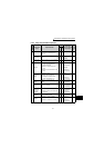
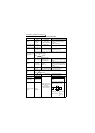
Module device numbers and terminals to be checked
(Assumes the use of an analog meter.)
CAUTION
•Before measurement, check that the smoothing capacitor is discharged.
•At the time of discontinuity, the measured value is almost ∞. When there is an
instantaneous continuity, due to the smoothing capacitor, the tester may not
indicate ∞. At the time of continuity, the measured value is several to several
ten's-of ohms depending on the module type, circuit tester type, etc. If all
measured values are almost the same, the modules are without fault.
Tester Polarity
Process
value
Tester Polarity
Process
value
Converter
Module
D1
R P Discontinuity
D4
RNContinuity
P R Continuity N R Discontinuity
D2
S P Discontinuity
D5
SNContinuity
P S Continuity N S Discontinuity
D3
T P Discontinuity
D6
TNContinuity
P T Continuity N T Discontinuity
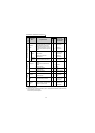
Inverter
Module
TR1
U P Discontinuity
TR4
UNContinuity
P U Continuity N U Discontinuity
TR3
V P Discontinuity
TR6
VNContinuity
P V Continuity N V Discontinuity
TR5
W P Discontinuity
TR2
WNContinuity
P W Continuity N W Discontinuity
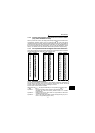
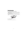
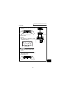
Converter module Inverter module
D1 D2 D3
D4 D5 D6
TR1 TR3 TR5
TR4 TR6 TR2
U
V
W
C
R
S
T
P
N