


36
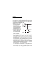
Input terminals
• Digital indicator
Since the digital indicator counts and displays the number of pulses, adjust it from
the operation panel or parameter unit.
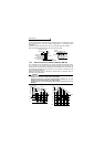
The inverter output, at which the reference pulses of 1440 pulses/s are output, can
be set in Pr. 55 when frequency monitoring is used as reference, or in Pr. 56 when
current monitoring is used as reference.
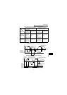
[Example] 1. To set the output across FM-SD to 1440 pulses/s at the inverter output
frequency of 120Hz, set "120" (Hz) in Pr. 55. (Factory setting: 60Hz)
2. To set the output across FM-SD to 1440 pulses/s at the inverter output
current of 15A, set "15" (A) in Pr. 56. (Factory setting: rated inverter
current)
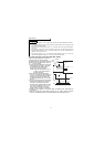
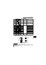
1.4.5 Control circuit common terminals (SD, 5, SE)
Terminals SD, 5, and SE are all common terminals (0V) for I/O signals and are isolated
from each other.
Terminal SD is a common terminal for the contact input terminals (STF, STR, RH, RM,
AU) and frequency output signal (FM).
Terminal 5 is a common terminal for the frequency setting analog input signals. It
should be protected from external noise using a shielded or twisted cable.
Terminal SE is a common terminal for the open collector output terminal (RUN).
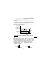
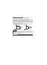
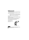
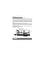
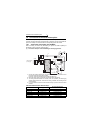
1.4.6 Signal inputs by contactless switches
If a transistor is used instead of a
contacted switch as shown on the
right, the input signals of the
inverter can control terminals STF,
STR, RH, RM, AU.
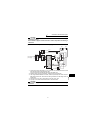
REMARKS
1.When using an external transistor connected to an external power supply, use terminal PC
to prevent a malfunctions due to undesirable currents. (Refer to page 26.)
2.Note that an SSR (solid-state relay) has a relatively large leakage current at OFF time and it
may be accidentally input to the inverter.
+24V
STF, etc.
SD
Inverter
External signal input using transistor