155
Communication parameters
2
FUNCTIONS
8
All parameter
clear
HFC
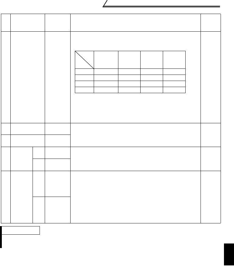
All parameters return to the factory settings.
Any of four different all clear operations are performed
according to the data.
When all parameter clear is executed for H9696 or
H9966, communication-related parameter settings also
return to the factory settings. When resuming operation,
set the parameters again.
* Pr. 75 is not cleared.
4 digits
9
Parameter
read
H00 to
H63
Refer to the "Instruction Code List" (page 206) and write
and/or read the values as required.
When setting Pr.100 and later, set link parameter
expansion setting.
4 digits
10
Parameter
write
H80 to
HE3
11
Link
parameter
expansion
setting
Read H7F
Set any of H00 to H09 to change the parameter settings.
For details of the settings, refer to the parameter
instruction code list (page 206).
2 digits
Write HFF
12
Second
parameter
changing
(Code
HFF = 1)
Read H6C
When setting the bias/gain (instruction code H5E to H61,
HDE to HE1) parameters
H00: Frequency (*1)
H01: Analog
H02: Analog value of terminal (*2)
*1. The gain frequencies may also be written using Pr.
38 and Pr. 39 (instruction codes A6 and A7).
*2. When a voltage is given to the external terminal to
make bias or gain calibration, the data value written
is 4 digits.
2 digits
Write HEC
REMARKS
For the instruction codes HFF, HEC, their set values are held once they are written, but
changed to 0 when the inverter is reset or all clear is performed.
No. Item
Instruction
Code
Description
Number
of Data
Digits
Commu-
nication
Pr.
Calibra
-tion
Pr
Other
Pr.*
HEC
HFF
H9696 { × {{
H9966 { {{{
H5A5A ××{{
H55AA × {{{
Pr.
Data


