


65
4-3 Program Capacity
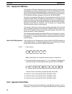
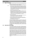
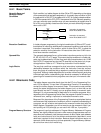
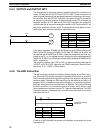
The maximum user program size varies with the amount of UM allocated to ex-
pansion DM and the I/O Comment Area. Approximately 10.1 KW are available
for the ladder program when 3 KW are allocated to expansion DM and 2 KW are
allocated to I/O comments as shown below. Refer to the
3-10 UM Area
for further
information on UM allocation.
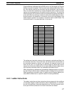
DM
6144
PC
Setup
Reserved
Expansion
DM Area
I/O Comment
Area
Ladder program
Variable size
Ladder Program Area (15.1 KW)Fixed DM Area
DM
6600
DM
6655
DM
7000
DM
9999
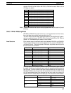
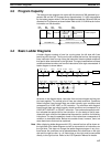
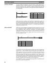
4-4 Basic Ladder Diagrams
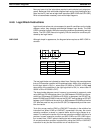
A ladder diagram consists of one line running down the left side with lines
branching off to the right. The line on the left is called the bus bar; the branching
lines, instruction lines or rungs. Along the instruction lines are placed conditions
that lead to other instructions on the right side. The logical combinations of these
conditions determine when and how the instructions at the right are executed. A
ladder diagram is shown below.
00000 06315
Instruction
Instruction
00403
00001
HR 0109 LR 250325208 24400
00501 00502 00503 00504
24401
00100 00002
00010
00011
00003 HR 0050 00007 TIM 001 LR 0515
21001 21002
00405
21005 21007
As shown in the diagram above, instruction lines can branch apart and they can
join back together. The vertical pairs of lines are called conditions. Conditions
without diagonal lines through them are called normally open conditions and
correspond to a LOAD, AND, or OR instruction. The conditions with diagonal
lines through them are called normally closed conditions and correspond to a
LOAD NOT, AND NOT, or OR NOT instruction. The number above each condi-
tion indicates the operand bit for the instruction. It is the status of the bit asso-
ciated with each condition that determines the execution condition for following
instructions. The way the operation of each of the instructions corresponds to a
condition is described below. Before we consider these, however, there are
some basic terms that must be explained.
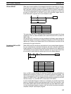
Note When displaying ladder diagrams with LSS, a second bus bar will be shown on
the right side of the ladder diagram and will be connected to all instructions on
the right side. This does not change the ladder-diagram program in any func-
tional sense. No conditions can be placed between the instructions on the right
side and the right bus bar, i.e., all instructions on the right must be connected
directly to the right bus bar. Refer to the
LSS Operation Manual
for details.
Basic Ladder Diagrams Section 4-4