


58
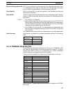
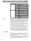
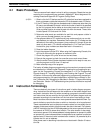
The following table lists the possible error codes and corresponding errors.
Error severity Error code Error
Fatal errors 00 Power Interruption
01 to 99 System error (FALS)
9F Cycle time error
C0 to C2 I/O bus error
E0 Input-output I/O table error
E1 Too many Units
F0 No END(01) instruction
F1 Memory error
Non-fatal errors 01 to 99 System error (FAL)
8A Interrupt Input error
8B Interrupt program error
9A Group 2 High-density I/O error
9B PC Setup error
9D UM Memory Cassette transfer error
B0 to B1 Remote I/O error
D0 Special I/O error
E7 I/O table verification error
F7 Battery error
F8 Cycle time overrun
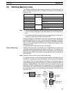
Operation When the first error code is generated with AR 0715 (Error History Enable Bit)
turned ON, the relevant data will be placed in the error record after the one indi-
cated by the History Record Pointer (initially this will be record 1) and the Pointer
will be incremented. Any other error codes generated thereafter will be placed in
consecutive records until the last one is used. Processing of further error records
is based on the status of AR 0713 (Error History Overwrite Bit).
If AR 0713 is ON and the Pointer contains 000A, the next error will be written into
record 10, the contents of record 10 will be moved to record 9, and so on until the
contents of record 1 is moved off the end and lost, i.e., the area functions like a
shift register. The Record Pointer will remain set to 000A.
If AR 0713 is OFF and the Pointer reaches 000A, the contents of the Error Histo-
ry Error will remain as it is and any error codes generate thereafter will not be
recorded until AR 0713 is turned OFF or until the Error History Area is reset.
The Error History Area can be reset by turning ON and then OFF
AR 0714 (Error History Reset Bit). When this is done, the Record Pointer will be
reset to 0000, the Error History Area will be reset (i.e., cleared), and any further
error codes will be recorded from the beginning of the Error History Area.
AR 0715 (Error History Enable Bit) must be ON to reset the Error History Area.
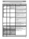
3-6-4 PC Setup
The PC Setup contains settings that determine C200HS operation. Data in the
PC Setup can be changed with a Programming Console or LSS if UM is not
write-protected by pin 1 of the CPU’s DIP switch. Refer to page 23 for details on
changing DIP switch pin settings.
The PC can be operated with the default PC Setup, which requires changing
only when customizing the PC’s operating environment to application needs.
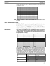
The PC Setup parameters are described in the following table. Refer to
Appen-
dix E PC Setup
for more details on these parameters.
DM Area Section 3-6