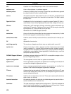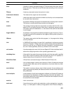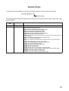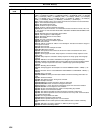
Index
500
OR:
4–1 to 4–6
69 ;
5–1 to 5–14
129
combining with AND: 4−1 to 4−6 69
OR LD:
4–1 to 4–6
72 ;
5–1 to 5–14
130
combining with AND LD: 4−1 to 4−6 73
use in logic blocks: 4−1 to 4−6 73
OR NOT:
4–1 to 4–6
69 ;
5–1 to 5–14
129
ORW(35):
5–20 to 5–23
251
OUT:
4–1 to 4–6
70 ;
5–1 to 5–14
130
OUT NOT:
4–1 to 4–6
70 ;
5–1 to 5–14
130
PID(––):
5–20 to 5–23
242
RECV(98):
5–24 on
296
RET(93):
5–20 to 5–23
259
ROL(27):
5–15 to 5–17
155
ROOT(72):
5–18 to 5–19
217
ROR(28):
5–15 to 5–17
155
RSET:
5–1 to 5–14
133
RXD(––):
5–24 on
300
SBB(51):
5–20 to 5–23
221
SBN(92):
5–20 to 5–23
259
SBS(91):
5–20 to 5–23
257
SCAN(18):
5–24 on
279
SCL(––):
5–18 to 5–19
198
SDEC(78):
5–18 to 5–19
191
SEC(65):
5–18 to 5–19
183
SEND(90):
5–24 on
294
SET:
5–1 to 5–14
133
SFT(10):
5–15 to 5–17
150
SFTR(84):
5–15 to 5–17
152
SLD(74):
5–15 to 5–17
156
SNXT(09):
5–24 on
269
SRCH(––):
5–24 on
292 , 293
SRD(75):
5–15 to 5–17
156
STC(40):
5–18 to 5–19
205
STEP(08):
5–24 on
269
SUB(31):
5–18 to 5–19
207
SUBL(55):
5–18 to 5–19
209
SUM(––):
5–20 to 5–23
237
TCMP(85):
5–15 to 5–17
175
TERM(48):
4–1 to 4–6
78 ;
5–24 on
283
terminology:
4–1 to 4–6
64
TIM:
5–1 to 5–14
139
TIMH(15):
5–1 to 5–14
143
TKY(––):
5–24 on
314
TRSM(45):
5–24 on
280
TTIM(87):
5–1 to 5–14
144
TXD(––):
5–24 on
302
WDT(94):
5–24 on
284
WSFT(16):
5–15 to 5–17
157
XCHG(73):
5–15 to 5–17
162
XFER(70):
5–15 to 5–17
161
XFRB(62):
5–15 to 5–17
168
XNRW(37):
5–20 to 5–23
253
XORW(36):
5–20 to 5–23
252
ZCP(88):
5–15 to 5–17
176
ZCPL(––):
5–15 to 5–17
177
instruction sets
ADBL(––):
5–20 to 5–23
225
NEG(––):
5–18 to 5–19
202
NEGL(––):
5–18 to 5–19
203
SBBL(––):
5–20 to 5–23
227
instructions
advanced I/O:
5–24 on
304
designations when inputting:
4–7 on
94
instruction set lists:
5–1 to 5–14
125
IORF(97):
6–4 on
339
mnemonics list, ladder:
5–1 to 5–14
125
instructions tables:
sec1
8
interlocks:
5–1 to 5–14
135–137
using self-maintaining bits:
4–7 on
109
interrupts:
5–20 to 5–23
253
control:
5–20 to 5–23
262
IOM data, reading/writing Memory Cassette data:
sec9
387
IOM HOLD BIT STATUS, PC Setup:
sec3
59
IR area:
sec3
31–33
J
jump numbers:
5–1 to 5–14
137
jumps:
5–1 to 5–14
137–138
K
keyboard mapping:
sec7
368
expansion keyboard mapping:
sec7
367
L
ladder diagram
branching:
4–7 on
103
IL(02) and ILC(03): 4−7 on 105
using TR bits: 4−7 on 103
controlling bit status
using DIFU(13) and DIFD(14): 4−7 on 109 ;
5−1 to 5−14 131ć132
using KEEP(11): 5−1 to 5−14 133ć139
using OUT and OUT NOT: 4−1 to 4−6 70
using SET and RSET: 5−1 to 5−14 133
converting to mnemonic code:
4–1 to 4–6
66–78
display via LSS:
4–1 to 4–6
65
instructions
combining, AND LD and OR LD: 4−1 to 4−6
73
controlling bit status
using KEEP(11): 4−7 on 109
using OUT and OUT NOT: 5−1 to 5−14 130
format: 5−1 to 5−14 118
notation:
5–1 to 5–14
118
structure:
4–1 to 4–6
65
using logic blocks:
4–1 to 4–6
71
ladder diagram instructions:
5–1 to 5–14
129–130
Ladder Support Software.
See
peripheral devices
LEDs.
See
CPU indicators
leftmost, definition:
sec3
27
Link System, flags and control bits:
sec3
39–41
Link Units
See also
Units
flags:
sec3
54
PC cycle time:
6–1 to 6–3
323
logic block instructions, converting to mnemonic code:
4–1 to
4–6
71–77
logic blocks.
See
ladder diagram
logic instructions:
5–20 to 5–23
249–253
LR area:
sec3
61
LSS.
See
peripheral devices
M
mapping, expansion keyboard mapping:
sec7
367
memory all clear:
4–1 to 4–6
82


