


443
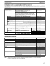
Appendix B
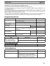
Programming Instructions
A PC instruction is input either by pressing the corresponding Programming Console key(s) (e.g., LD, AND, OR,
NOT) or by using function codes. To input an instruction with its function code, press FUN, the function code, and
then WRITE. Refer to the pages listed programming and instruction details.
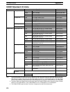
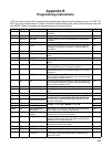
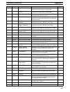
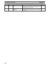
Code Mnemonic Name Function Page
— AND AND Logically ANDs status of designated bit with execution
condition.
129
— AND LD AND LOAD Logically ANDs results of preceding blocks. 130
— AND NOT AND NOT Logically ANDs inverse of designated bit with execution
condition.
129
— CNT COUNTER A decrementing counter. 145
— LD LOAD Used to start instruction line with the status of the desig-
nated bit or to define a logic block for use with AND LD
and OR LD.
129
— LD NOT LOAD NOT Used to start instruction line with inverse of designated bit. 129
— OR OR Logically ORs status of designated bit with execution con-
dition.
129
— OR LD OR LOAD Logically ORs results of preceding blocks. 130
— OR NOT OR NOT Logically ORs inverse of designated bit with execution con-
dition.
129
— OUT OUTPUT Turns ON operand bit for ON execution condition; turns
OFF operand bit for OFF execution condition.
130
— OUT NOT OUTPUT NOT Turns operand bit OFF for ON execution condition; turns
operand bit ON for OFF execution condition (i.e., inverts
operation).
130
— RSET RESET Turns the operand bit OFF when the execution condition is
ON, and does not affect the status of the operand bit when
the execution condition is OFF.
133
— SET SET Turns the operand bit ON when the execution condition is
ON, and does not affect the status of the operand bit when
the execution condition is OFF.
133
— TIM TIMER ON-delay (decrementing) timer operation. 139
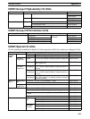
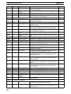
00 NOP NO OPERATION Nothing is executed and program moves to next instruc-
tion.
138
01 END END Required at the end of the program. 138
02 IL INTERLOCK
If interlock condition is OFF, all outputs are turned OFF
and all timer PVs reset between this IL
(
02
)
and the next
135
03 ILC INTERLOCK CLEAR
and
all
timer
PVs
reset
between
this
IL(02)
and
the
next
ILC(03). Other instructions are treated as NOP; counter
PVs are maintained.
135
04 JMP JUMP
If jump condition is OFF, all instructions between JMP(04)
d th di JME(05) i d
137
05 JME JUMP END
j, ()
and the corresponding JME(05) are ignored.
137
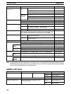
(@)06 FAL FAILURE ALARM
AND RESET
Generates a non-fatal error and outputs the designated
FAL number to the Programming Console.
275
07 FALS SEVERE FAILURE
ALARM
Generates a fatal error and outputs the designated FALS
number to the Programming Console.
275
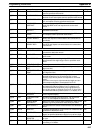
08 STEP STEP DEFINE When used with a control bit, defines the start of a new
step and resets the previous step. When used without N,
defines the end of step execution.
266
09 SNXT STEP START Used with a control bit to indicate the end of the step, reset
the step, and start the next step.
266
10 SFT SHIFT REGISTER Creates a bit shift register. 150
11 KEEP KEEP Defines a bit as a latch controlled by set and reset inputs. 133
12 CNTR REVERSIBLE
COUNTER
Increases or decreases PV by one whenever the incre-
ment input or decrement input signals, respectively, go
from OFF to ON.
148