33
Group-2 High-density I/O Units and B7A Interface Units are allocated words be-
tween IR 030 and IR 049 according to I/O number settings made on them and do
not use the words allocated to the slots in which they are mounted. For 32-point
Units, each Unit is allocated two words; for 64-point Units, each Unit is allocated
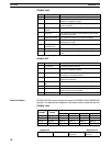
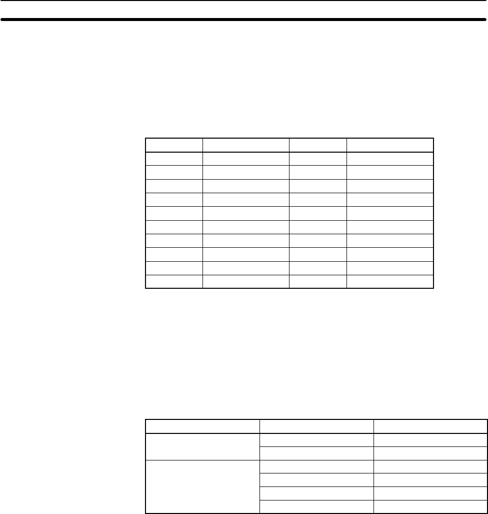
four words. The words allocated for each I/O number are in the following tables.
Any words or part of words not used for I/O can be used as work words or bits in
programming.
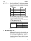
32-point Units 64-point Units
I/O number
Words I/O number Words
0 IR 30 to IR 31 0 IR 30 to IR 33
1 IR 32 to IR 33 1 IR 32 to IR 35
2 IR 34 to IR 35 2 IR 34 to IR 37
3 IR 36 to IR 37 3 IR 36 to IR 39
4 IR 38 to IR 39 4 IR 38 to IR 41
5 IR 40 to IR 41 5 IR 40 to IR 43
6 IR 42 to IR 43 6 IR 42 to IR 45
7 IR 44 to IR 45 7 IR 44 to IR 47
8 IR 46 to IR 47 8 IR 46 to IR 49
9 IR 48 to IR 49 9 Cannot be used.
When setting I/O numbers on the High-density I/O Units and B7A Interface
Units, be sure that the settings will not cause the same words to be allocated to
more than one Unit. For example, if I/O number 0 is allocated to a 64-point Unit,
I/O number 1 cannot be used for any Unit in the system.
Group-2 High-density I/O Units and B7A Interface Units are not considered Spe-
cial I/O Units and do not affect the limit to the number of Special I/O Units allowed
in the System, regardless of the number used.
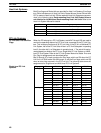
The words allocated to Group-2 High-density I/O Units correspond to the con-
nectors on the Units as shown in the following table.
Unit Word Connector/row
32-point Units
First Row A
Second Row B
64-point Units
First CN1, row A
Second CN1, row B
Third CN2, row A
Fourth CN2, row B
Note Group-2 High-density I/O Units and B7A Interface Units cannot be mounted to
Slave Racks.
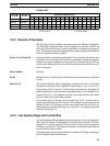
3-4 SR (Special Relay) Area
The SR area contains flags and control bits used for monitoring PC operation,
accessing clock pulses, and signalling errors. SR area word addresses range
from 236 through 511; bit addresses, from 23600 through 51115.
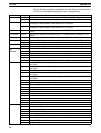
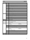
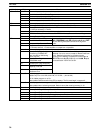
The following table lists the functions of SR area flags and control bits. Most of
these bits are described in more detail following the table. Descriptions are in
order by bit number except that Link System bits are grouped together.
Unless otherwise stated, flags are OFF until the specified condition arises, when
they are turned ON. Restart bits are usually OFF, but when the user turns one
ON then OFF, the specified Link Unit will be restarted. Other control bits are OFF
until set by the user.
Allocation for Group-2
High-density I/O Units and
B7 Interface Units
SR Area Section 3-4


