


273
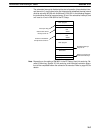
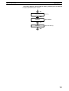
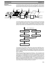
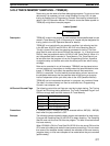
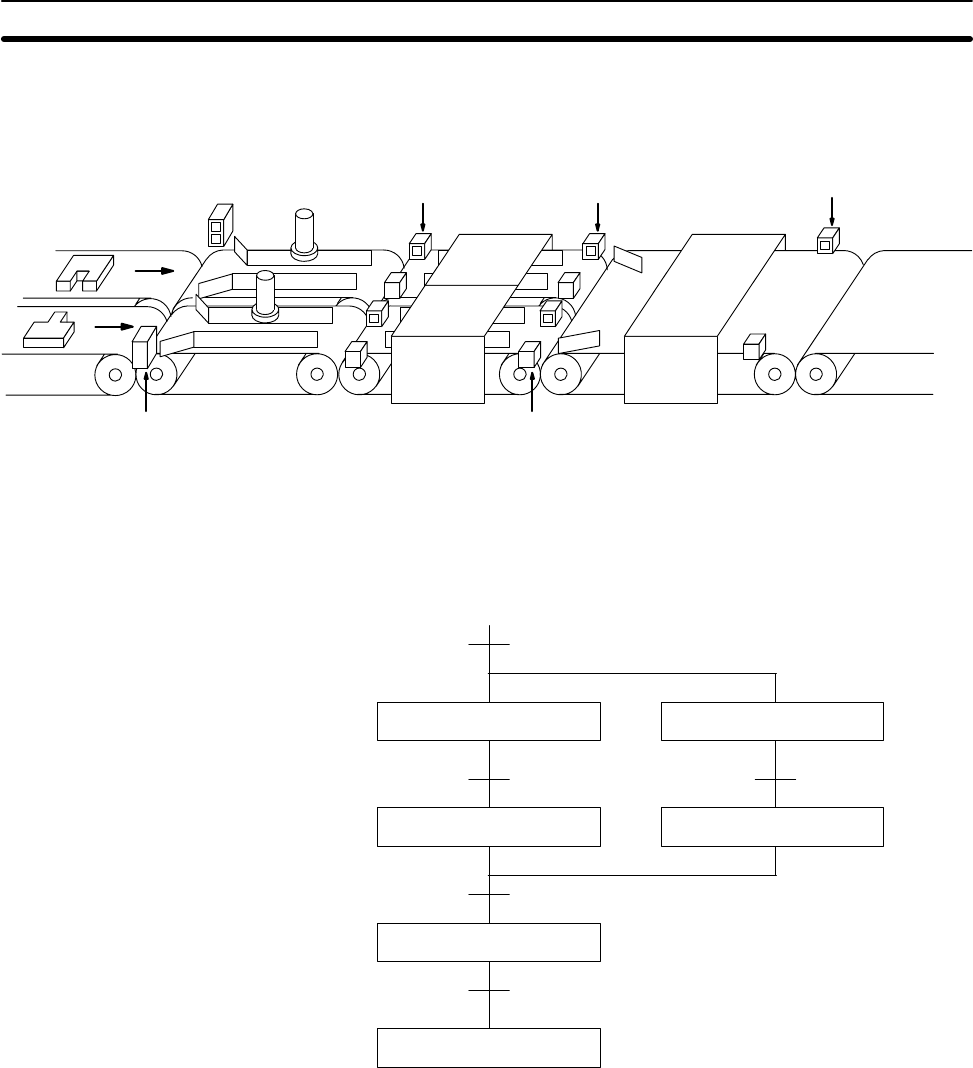
The following process requires that two parts of a product pass simultaneously
through two processes each before they are joined together in a fifth process.
Various sensors are positioned to signal when processes are to start and end.
Process C
SW1
SW2
Process A
SW3
SW4
Process D
Process B
Process E
SW6
SW5 SW7
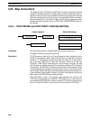
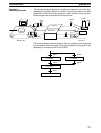
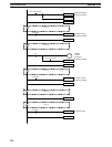
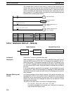
The following diagram demonstrates the flow of processing and the switches
that are used for execution control. Here, process A and process C are started
together. When process A finishes, process B starts; when process C finishes,
process D starts. When both processes B and D have finished, process E starts.
Process A
Process E
End
Process C
SW7
Process B Process D
SW3
SW4
SW 1 and SW2 both ON
SW5 and SW6 both ON
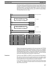
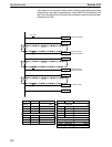
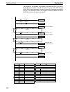
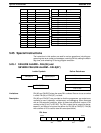
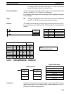
The program for this operation, shown below, starts with two SNXT(09) instruc-
tions that start processes A and C. These instructions branch from the same in-
struction line and are always executed together, starting steps for both A and C.
When the steps for both A and C have finished, the steps for process B and D
begin immediately.
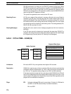
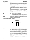
When both process B and process D have finished (i.e., when the status for both
of them is “ON”, but SW5 and SW6 have turned ON), processes B and D are
reset together by the SNXT(09) at the end of the programming for process B.
Although there is no SNXT(09) at the end of process D, the control bit for it is
turned OFF by executing SNXT(09) LR 0004. This is because the OUT for LR
0003 is in the step reset by SNXT(09) LR 0004, i.e., LR 003 is turned OFF when
SNXT(09) LR 0004 is executed Process B is thus reset directly and process D is
reset indirectly before executing the step for process E.
Example 3:
Parallel Execution
Step Instructions Section 5-24