


64
4-1 Basic Procedure
There are several basic steps involved in writing a program. Sheets that can be
copied to aid in programming are provided in
Appendix F Word Assignment Re-
cording Sheets
and
Appendix G Program Coding Sheet
.
1, 2, 3...
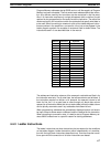
1. Obtain a list of all I/O devices and the I/O points that have been assigned to
them and prepare a table that shows the I/O bit allocated to each I/O device.
2. If the PC has any Units that are allocated words in data areas other than the
IR area or are allocated IR words in which the function of each bit is specified
by the Unit, prepare similar tables to show what words are used for which
Units and what function is served by each bit within the words. These Units
include Special I/O Units and Link Units.
3. Determine what words are available for work bits and prepare a table in
which you can allocate these as you use them.
4. Also prepare tables of TC numbers and jump numbers so that you can allo-
cate these as you use them. Remember, the function of a TC number can be
defined only once within the program; jump numbers 01 through 99 can be
used only once each. (TC number are described in
5-14 Timer and Counter
Instructions
; jump numbers are described later in this section.)
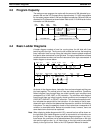
5. Draw the ladder diagram.
6. Input the program into the CPU. When using the Programming Console, this
will involve converting the program to mnemonic form.
7. Check the program for syntax errors and correct these.
8. Execute the program to check for execution errors and correct these.
9. After the entire Control System has been installed and is ready for use, exe-
cute the program and fine tune it if required.
10. Make a backup copy of the program.
The basics of ladder-diagram programming and conversion to mnemonic code
are described in
4-4 Basic Ladder Diagrams
. Preparing for and inputting the pro-
gram via the Programming Console are described in
4-5 The Programming
Console
through
4-7 Inputting, Modifying, and Checking the Program
. The rest
of Section 4 covers more advanced programming, programming precautions,
and program execution. All special application instructions are covered in
Sec-
tion 5 Instruction Set
. Debugging is described in
Section 7 Program Monitoring
and Execution
.
Section 10 Troubleshooting
also provides information required
for debugging.
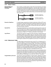
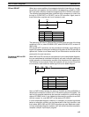
4-2 Instruction Terminology
There are basically two types of instructions used in ladder-diagram program-
ming: instructions that correspond to the conditions on the ladder diagram and
are used in instruction form only when converting a program to mnemonic code
and instructions that are used on the right side of the ladder diagram and are
executed according to the conditions on the instruction lines leading to them.
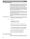
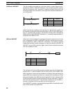
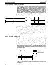
Most instructions have at least one or more operands associated with them. Op-
erands indicate or provide the data on which an instruction is to be performed.
These are sometimes input as the actual numeric values, but are usually the ad-
dresses of data area words or bits that contain the data to be used. For instance,
a MOVE instruction that has IR 000 designated as the source operand will move
the contents of IR 000 to some other location. The other location is also desig-
nated as an operand. A bit whose address is designated as an operand is called
an operand bit; a word whose address is designated as an operand is called an
operand word. If the actual value is entered as a constant, it is preceded by # to
indicate that it is not an address.
Other terms used in describing instructions are introduced in
Section 5 Instruc-
tion Set
.
Instruction Terminology Section 4-2