Standard Models Appendix A
440
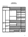
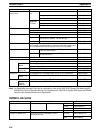
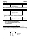
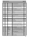
Optical Power Tester
Name Specifications Head Unit Model number
Optical Power Tester (see note)
(provided with a connector adapter,
light source unit, small single-head
plug, hard case, and AC adapter)
SYSMAC BUS:
C200H-RM001-PV1
C200H-RT001/RT002-P
C500-RM001-(P)V1
C500-RT001/RT002-(P)V1
S3200-CAT2822
(provided with the
Tester)
S3200-CAT2820
Note: There is no difference between the light source unit and connector adapter for the Head Unit and those for
the Optical Power Tester.
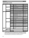
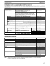
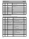
Head Unit
Name Specifications Model number
Head Unit (a set consisting of light
source unit and connector adapter)
(see note)
SYSMAC BUS:
C200H-RM001-PV1
C200H-RT001/RT002-P
S3200-CAT2822
SYSMAC NET:
S3200-LSU03-V1/LSU03-01E
C500-SNT31-V4
3G8FX-TM111
3G8SX-TM111
S3200-CAT3202
Note: Use a proper Head Unit model for the optical module to be used. If two types of optical modules (unit type
and board type) are used, order an Optical Power Tester plus a proper Head Unit model.
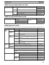
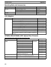
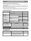
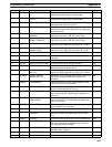
Master Fiber Set
Name Specifications Model number
Master Fiber Set (1 m) S3200-CAT3202 (SYSMAC NET, NSB, NSU, Bridge) S3200-CAT3201
S3200-CAT2002/CAT2702 (SYSMAC NET, SYSMAC
LINK)
S3200-CAT2001H
S3200-CAT2822 (SYSMAC BUS) S3200-CAT2821
Note 1. The Master Fiber Set is used in combination with the Optical Power Tester to check the optical levels of
optical fiber cables connected to optical fiber cable connectors.
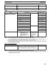
2. Optical fiber cables must be prepared and connected by specialists.
3. The Optical Power Tester, Head Unit, Master Fiber set, and Optical Fiber Assembling Tool are required
to connect optical fiber cables.
SYSMAC LINK/SYSMAC NET Link Optical Fiber Products
Optical Fiber Cables for SYSMAC LINK and SYSMAC NET Link Systems
Use hard-plastic-clad quartz optical fiber (H-PCF) cables for SYSMAC LINK and SYSMAC NET Link Systems.
H-PCF cables are available with connectors already attached, or cables and connectors can be purchased sepa-
rately and assembled by the user. Refer to the
System Manual
for the SYSMAC LINK or SYSMAC NET Link Sys-
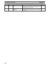
tems for assembly procedures. Models numbers for H-PCF cables with connecters attached are provided in the
following illustration.
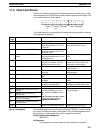
S3200-CNjjj-jj-jj
Cable length
201: 2 m
501: 5 m
102: 10 m
152: 15 m
202: 20 m
Blank: Over 20 m
(Specify.)
Connectors
20-25: Full-lock connector on
one end, half-lock con-
nector on other end.
25-25: Half-lock connectors
on both ends.
Model Numbers for H-PCF Cables with Connectors


