


46
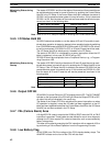
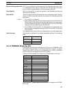
3-4-20 Peripheral Port Communications Areas
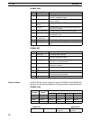
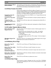
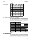
Peripheral Port Error Code SR bits 26408 to 26411 are set when there is a peripheral port error in the Gener-
al I/O Mode.
Setting Error type
0 No error
1 Parity error
2 Framing error
3 Overrun error
F Connected in Peripheral Mode
SR bit 26412 turns ON when there is a peripheral port communication error (ef-
fective in General I/O Mode).
SR bit 26413 turns ON when the C200HS is ready to transmit data in General I/O
Mode.
SR bit 26414 turns ON when the C200HS has completed reading data from a
peripheral device. Effective in General I/O Mode.
SR bit 26415 turns ON when data overflow occurs following the reception of
data. Effective in General I/O Mode.
SR areas 26600 to 26615 contains the number of peripheral port receptions in
General I/O Mode (BCD).
SR bit 26705 turns ON when the C200HS is ready to transmit to the Host Link
Unit.
SR bit 26713 turns ON when the C200HS is ready to receive data from the Host
Link.
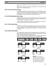
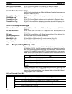
3-4-21 Memory Cassette Areas
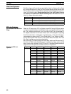
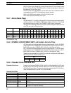
Memory Cassette Contents SR areas 26900 to 26907 indicate memory type contained on the Memory Cas-
sette.
Memory Type Code
Nothing 00
UM 01
IOM 02
Memory Cassette Capacity SR areas 26908 to 26910 indicate memory capacity of the Memory Cassette.
Capacity Code
0 KW (no board mounted) 0
16 KW 3
SR bit 26914 turns ON when EEPROM Memory Cassette is protected or
EPROM Memory Cassette is mounted.
Memory Cassette Flag SR bit 26915 turns ON when a Memory Cassette is mounted.
Save UM to Cassette Flag SR bit 27000 turns ON when UM data is read to a Memory Cassette in Program
Mode. Bit will automatically turn OFF. An error will be produced if turned ON in
any other mode.
SR bit 27001 turns ON when data is loaded into UM from a Memory Cassette in
Program Mode. Bit will automatically turn OFF. An error will be produced if
turned ON in any other mode.
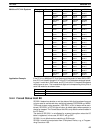
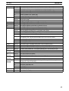
Peripheral Port
Communication Error Bit
Peripheral Port Send Ready
Flag
Peripheral Port Reception
Completed Flag
Peripheral Port Reception
Overflow Flag
Peripheral Reception
Counter
Host Link Level 0 Send
Ready Flag
Host Link Level 1 Receive
Ready Flag
EEPROM/EPROM Memory
Cassette Mounted Flag
Load UM from Cassette
Flag
SR Area Section 3-4