


300
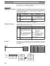
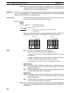
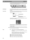
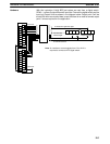
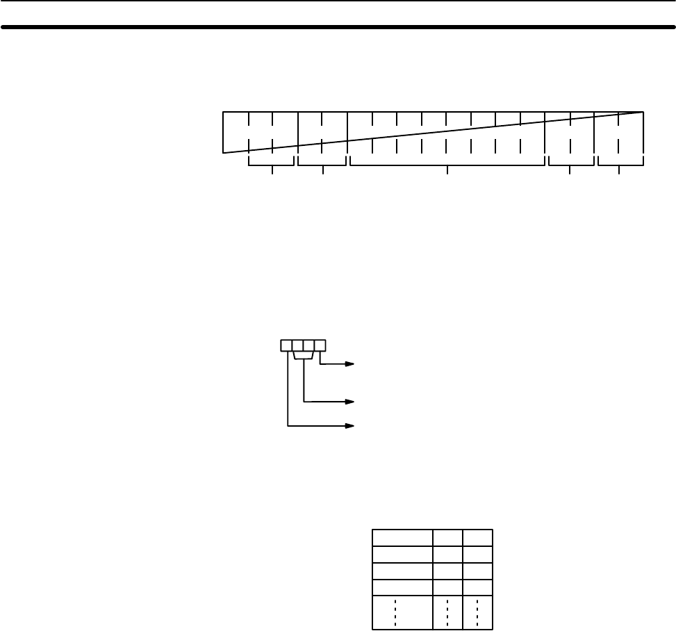
The following diagram shows the format for host link command (TXD) sent from
the C200HS. The C200HS automatically attaches the prefixes and suffixes,
such as the node number, header, and FCS.
@ X X X X X X ......... X X X ∗ CR
Header
code (EX)
Data (122 ASCII characters max.) FCSNode
number
Terminator
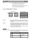
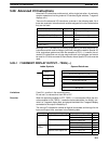
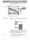
RS-232C Mode N must be BCD from #0000 to #0256. The value of the control word determines
the port from which data will be output and the order in which data will be written
to memory.
Control Word The value of the control word determines the port from which data will be read
and the order in which data will be written to memory.
Byte order 0: Most significant bytes first
1: Least significant bytes first
Not used. (Set to 00.)
Port 0: Specifies RS-232C port
(C200HS-CPU21-E/23-E/31-E/CPU33-E).
1: Specifies peripheral port.
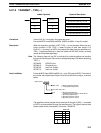
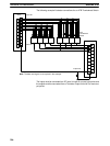
Digit number: 3210
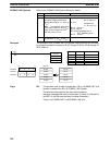
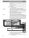
The specified number of bytes will be read from S through S+(NP2)–1 and trans-
mitted through the specified port.
MSB LSB
S12
S+1 3 4
S+2 5 6
S+3 7 8
When digit 0 of C is 0, the bytes of source data shown above will be transmitted in
this order: 12345678...
When digit 0 of C is 1, the bytes of source data shown above will be transmitted in
this order: 21436587...
Note When start and end codes are specified the total data length should be 256 bytes
max., including the start and end codes.
Flags ER: Another device is not connected to the peripheral port.
There is an error in the communications settings (PC Setup) or the oper-
and settings.
Indirectly addressed DM word is non-existent. (Content of *DM word is
not BCD, or the DM area boundary has been exceeded.)
The source words (S to S+(N÷2)–1) exceed the data area.
26405: RS-232C Port Communications Enabled Flag
26413: Peripheral Port Communications Enabled Flag
26705: Host Link Unit #0 Communications Enabled Flag
26713: Host Link Unit #1 Communications Enabled Flag
Serial Communications Instructions Section 5-27