


387
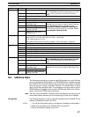
Word FunctionBit(s)
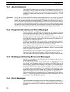
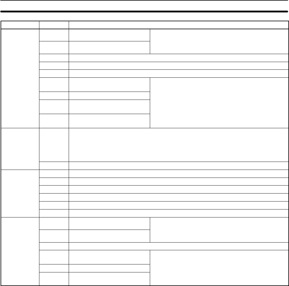
SR 270
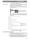
00 Save UM to Cassette Bit
Data transferred to Memory Cassette when Bit is turned
ON in PROGRAM mode. Bit will automaticall
y
turn OFF.
01 Load UM from Cassette Bit
ON
in
PROGRAM
mode
.
Bit
will
automatically
turn
OFF
.
An error will be produced if turned ON in any other
mode.
02 Collation Execution Flag
03 Collation NG Flag
04 to 11 Reserved by system (not accessible by user)
12 Transfer Error Flag: Not
PROGRAM mode
Data will not be transferred from UM to the Memory
Cassette if an error occurs (except for Board Checksum
E )Dtildif ti h k
13 Transfer Error Flag: Read Only
(
Error). Detailed information on checksum errors
occurring in the Memory Cassette will not be out
p
ut to
14 Transfer Error Flag: Insufficient
Capacity or No UM
occurr
i
ng
i
n
th
e
M
emory
C
asse
tt
e w
ill
no
t
b
e ou
t
pu
t
t
o
SR 272 because the information is not needed. Repeat
the transmission if SR 27015 is ON.
15 Transfer Error Flag: Board
Checksum Error
the
transmission
if
SR
27015
is
ON
.
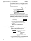
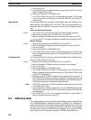
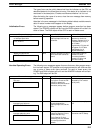
SR 271
00 to 07 Ladder program size stored in Memory Cassette
Ladder-only File: 04: 4 KW; 08: 8 KW; 12: 12 KW; ... (64: 64 KW)
00: No Ladder program or no file
Data updated at data transfer from CPU at startup. The file must begin in segment 0.
08 to 15 Ladder program size and type in CPU (Specifications are the same as for bits 00 to 07.)
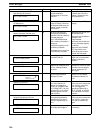
SR 272
00 to 10 Reserved by system (not accessible by user)
11 Memory Error Flag: PC Setup Checksum Error
12 Memory Error Flag: Ladder Checksum Error
13 Memory Error Flag: Instruction Change Vector Area Checksum Error
14 Memory Error Flag: Memory Cassette Online Disconnection
15 Memory Error Flag: Autoboot Error
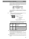
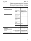
SR273
00 Save IOM to Cassette Bit
Data transferred to Memory Cassette when Bit is turned
ON in PROGRAM mode. Bit will automaticall
y
turn OFF.
01 Load IOM from Cassette Bit
ON
in
PROGRAM
mode
.
Bit
will
automatically
turn
OFF
.
An error will be produced if turned ON in any other
mode.
02 to 11 Reserved by system (not accessible by user)
12 Transfer Error Flag: Not
PROGRAM mode
Data will not be transferred from IOM to the Memory
Cassette if an error occurs (except for Read Only Error).
13 Transfer Error Flag: Read Only
(y)
14 Transfer Error Flag: Insufficient
Capacity or No IOM
9-3 UM Area Data
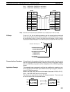
The following procedures can be used to read UM Area data from, write UM Area
data to, and compare UM Area data on an EEPROM Memory Cassette mounted
to a C200HS CPU. This UM Area data can include the user program, fixed DM
data such as the PC Setup, expansion DM data, I/O comment data, I/O table
data, and UM Area allocation data. The procedures cannot be used to write to
EPROM Memory Cassettes, which require a PROM writer. Refer to the LSS op-
eration manuals for PROM writer procedures.
Note The data inside the Memory Cassette should be protected by turning on the
write-protect switch whenever you are not planning to write to the Cassette.
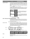
Writing Data The following procedure is used to write UM Area data from the C200HS CPU to
a Memory Cassette mounted in the CPU.
1, 2, 3...
1. Turn off the write-protect switch on the Memory Cassette to write-enable it.
2. Make sure that power to the C200HS CPU is turned OFF.
3. Mount the Memory Cassette to the CPU.
UM Area Data Section 9-3