


23
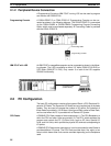
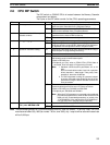
2-6 CPU DIP Switch
The DIP switch on C200HS CPUs is located between the Memory Cassette
compartment and battery.
The 6 pins on the DIP switch control 6 of the CPU’s operating parameters.
Pin no. Item Setting Function
1 Memory protect
ON Program Memory and read-only DM (DM 6144 to DM 6655)
data cannot be overwritten from a Peripheral Device.
OFF Program Memory and read-only DM (DM 6144 to DM 6655)
data can be overwritten from a Peripheral Device.
2 Automatic transfer of Memory
Cassette contents
ON The contents of the Memory Cassette will be automatically
transferred to the internal RAM at start-up.
OFF The contents will not be automatically transferred.
3 Message language
ON Programming Console messages will be displayed in English.
ggg
OFF Programming Console messages will be displayed in the
language stored in system ROM. (Messages will be displayed
in Japanese with the Japanese version of system ROM.)
4 Expansion instruction setting
ON Expansion instructions set by user. Normally ON when using a
host computer for programming/monitoring.
OFF Expansion instructions set to defaults.
5 Communications parameters
ON Standard communications parameters (see note) will be set for
the following serial communications ports.
• Built-in RS-232C port
• Peripheral port (only when a CQM1-CIF01/-CIF02 Cable is
connected. Does not apply to Programming Console.)
Note 1. Standard communications parameters are as fol-
lows:
Serial communications mode: Host Link or peripher-
al bus; start bits: 1; data length: 7 bits; parity: even;
stop bits: 2; baud rate: 9,600 bps
2. The CX-Programmer running on a personal comput-
er can be connected to the peripheral port via the pe-
ripheral bus using the above standard communica-
tions parameters.
OFF The communications parameters for the following serial
communications ports will be set in PC Setup as follows:
• Built-in RS-232C port: DM 6645 and DM 6646
• Peripheral port: DM 6650 and DM 6651
Note When the CX-Programmer is connected to the peripheral
port with the peripheral bus, either set bits 00 to 03 of DM
6650 to 0 Hex (for standard parameters), or set bits 12 to
15 of DM 6650 to 0 Hex and bits 00 to 03 of DM 6650 to 1
Hex (for Host Link or peripheral bus) separately.
6 Expansion TERMINAL mode
i h AR 0709 i ON
ON Expansion TERMINAL mode; AR 0712 ON.
setting when AR 0709 is ON
OFF Normal mode; AR 0712: OFF
Note The above settings apply to CPUs manufactured from July 1995 (lot number **75 for July 1995). For CPUs
manufactured before July 1995 (lot number **65 for June 1995), only 1 stop bit will be set and the baud rate
will be 2,400 bps.
CPU DIP Switch Section 2-6