


377
8-2-3 Wiring Ports
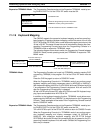
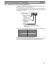
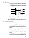
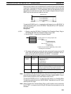
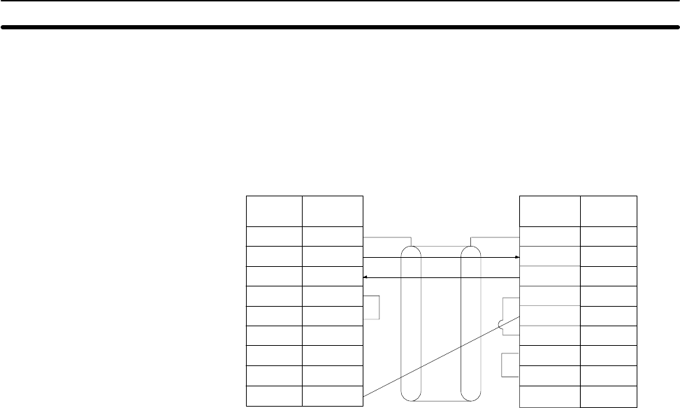
Use the wiring diagram shown below as a guide in wiring the port to the external
device. Refer to documentation provided with the computer or other external de-
vice for wire details for it.
The connections between the C200HS and a personal computer are illustrated
below as an example.
1
2
3
4
5
6
FG
SD
RD
RS
CS
–
–
–
SG
7
8
9
1
2
3
4
5
6
7
8
9
SD
RD
RS
CS
DSR
SG
–
9
DTR
C200HS Personal computer
SignalPin
No.
Signal Pin
No.
Shielded cable
–
Applicable Connectors
The following connectors are applicable. One plug and one hood are included
with the CPU.
Plug: XM2A-0901 (OMRON) or equivalent
Hood: XM2S-0901 (OMRON) or equivalent
Note Ground the FG terminal on the C200HS and at the computer to 100 Ω or less.
Refer to the
C200HS Installation Manual
and to the documentation for your com-
puter for details.
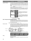
8-2-4 Host Link Communications
This section describes the PC Setup parameters and communications proce-
dure for the Host Link communications mode.
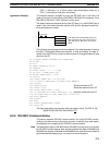
Host link communications were developed by OMRON to connect PCs and one
or more host computers by RS-232C cable, and to control PCs through commu-
nications from the host computer. Normally the host computer issues a com-
mand to a PC, and the PC automatically sends back a response. Thus the com-
munications are carried out without the PCs being actively involved. The PCs
also have the ability to initiate data transmissions when direct involvement is
necessary.
In general, there are two means for implementing host link communications.
One is based on C-mode commands, and the other on FINS (CV-mode) com-
mands. The C200HS supports C-mode commands only. For details on host link
communications, refer to
Section 11
Host Link Commands.
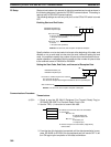
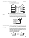
The C200HS supports Host Link communications either through the peripheral
or RS-232C port, or though Host Link Units (#0 and #1) mounted to the PC. The
Host Link Units include the C200H-LD201-V1, C200H-LD202-V1, and C200H-
LK101-PV1.
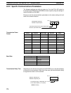
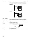
Note The leftmost two digits of DM 6645 and/or DM 6650 must be set to 00 to enable
the Host Link Mode. Also, set the rightmost two digits of DM 6645 and DM 6655
and all digits of DM 6646 and DM 6656 to the required communications parame-
ters before attempting to use Host Link communications.
Parameters for Host Link and RS-232C Communications
Section 8-2