


17
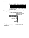
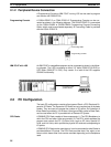
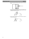
C200HS-CPU21-E/CPU23-E/CPU31-E/CPU33-E
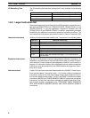
Memory Casette compartment
Bus connector:
Available only with the CPU31-E
and CPU33-E. Use this connector
when SYSMAC NET Link Unit or
SYSMAC LINK Unit is used.
RS-232C
connector
Cable connector for
peripheral devices
Battery/Switch compartment
Power fuse (MF51NR, 5.2 dia. x 20 mm):
C200HS-CPU21-E/CPU31-E: 2 A, 250 V
C200HS-CPU23-E/CPU33-E: 5 A, 125 V
Indicators
Removable terminal block
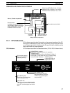
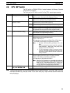
2-1-1 CPU Indicators
CPU indicators provide visual information on the general operation of the PC.
Although not substitutes for proper error programming using the flags and other
error indicators provided in the data areas of memory, these indicators provide
ready confirmation of proper operation.
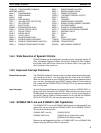
CPU Indicators CPU indicators are shown and described below. (CPU01-E/03-E shown below.)
COMM/COMM1 (orange):
Lights when a peripheral device is in operation.
COMM2 (orange):
Available only with the CPU21-E, CPU23-E, CPU31-E,
and CPU33-E. Lights when the CPU is communicating
via the RS-232C connector.
RUN indicator (green)
Lights when the PC is
operating normally.
POWER (green)
Lights when power is
supplied to the CPU.
OUT INHIBIT (red)
Lights when the Load OFF
flag (SR bit 25215) turns ON,
at which time all the outputs
are turned OFF.
ALM (blinking red)
Blinks if an error occurs that
does not stop the CPU.
ERR (solid red)
Lights if an error occurs that stops the
CPU, at which time the RUN indicator
turns OFF and the outputs are turned
OFF.
COMM
CPU Components Section 2-1