


299
5-27-2 TRANSMIT – TXD(––)
S: First source word
IR, SR, AR, DM, HR, TC, LR
C: Control word
IR, SR, AR, DM, HR, TC, LR, #
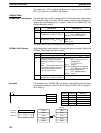
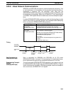
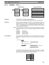
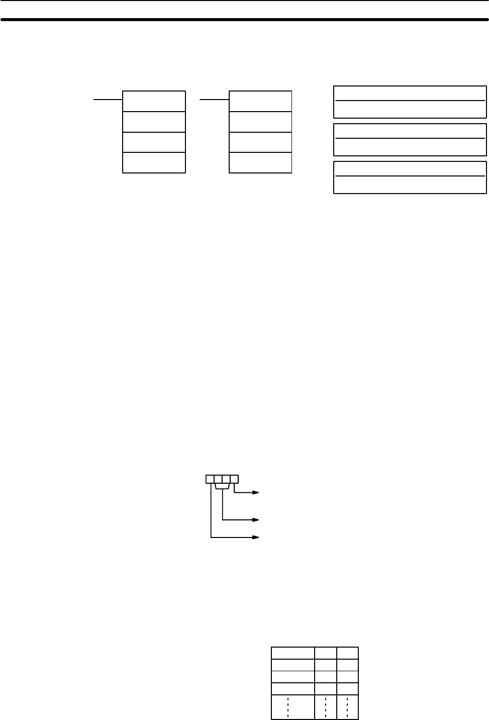
Ladder Symbols
Operand Data Areas
N: Number of bytes
IR, SR, AR, DM, HR, TC, LR, #
TXD(––)
S
C
N
@TXD(––)
S
C
N
Limitations S and S+(N÷2)–1 must be in the same data area.
N must be BCD from #0000 to #0256. (#0000 to #0061 in host link mode)
Description When the execution condition is OFF, TXD(––) is not executed. When the exe-
cution condition is ON, TXD(––) reads N bytes of data from words S to
S+(N÷2)–1, converts it to ASCII, and outputs the data from the specified port.
TXD(––) operates differently in host link mode and RS-232C mode, so these
modes are described separately.
Note The following flags will be ON to indicate that communications are possible
through the various ports. Be sure the corresponding flag is ON before executing
TXD(––).
SR 26405: RS-232C port
SR 26413: Peripheral port
SR 26705: Host Link Unit #0
SR 26713: Host Link Unit #1
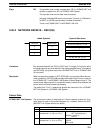
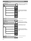
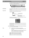
Host Link Mode N must be BCD from #0000 to #0061 (i.e., up to 122 bytes of ASCII). The value of
the control word determines the port from which data will be output, as shown
below.
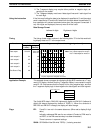
Byte order 0: Most significant bytes first
1: Least significant bytes first
Not used. (Set to 00.)
Port 0: Specifies RS-232C port
(C200HS-CPU21-E/23-E/31-E/CPU33-E).
1: Specifies peripheral port.
2: Specifies Host Link Unit #0
3: Specifies Host Link Unit #1
Digit number: 3210
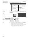
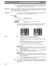
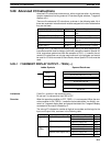
The specified number of bytes will be read from S through S+(N/2)–1, converted
to ASCII, and transmitted through the specified port. The bytes of source data
shown below will be transmitted in this order: 12345678...
MSB LSB
S12
S+1 3 4
S+2 5 6
S+3 7 8
Serial Communications Instructions Section 5-27