


59
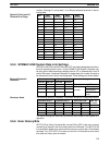
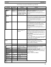
The PC Setup is allocated to DM 6600 through DM 6655.
Parameter Default Settings Remarks
STARTUP MODE
STARTUP
MODE
Programming
Console
mode selector
Programming Console
mode selector, previous
mode (i.e., the mode in
use last time power was
interrupted), PROGRAM,
MONITOR, or RUN
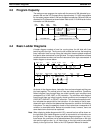
Determines the operating mode the PC will start in
when power is turned ON.
This setting is required for restart continuation.
Setting is effective from next time power is turned on
to the PC.
FORCED
STATUS
Don’t hold Hold or don’t hold Determines whether or not the status of the Forced
Status Hold Bit is maintained after power interruptions.
If the status of the Forced Status Hold Bit is not set to
be held, it will be turned OFF the next time the PC is
started and forced status will be cleared.
Setting is effective from next time power is turned on
to the PC.
IOM HOLD BIT
STATUS
Don’t hold Hold or don’t hold Determines whether or not the status of the IOM Hold
Bit is maintained after power interruptions. If the status
of the IOM Hold Bit is not set to be held, it will be
turned OFF the next time the PC is started and I/O
status will be cleared.
This setting is required for restart continuation.
Setting is effective from next time power is turned on
to the PC.
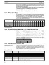
CYCLE TIME Variable Variable or minimum
Minimum setting: 1 to
9,999 ms
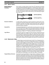
Determines whether or not a minimum cycle time is to
be used for user program execution. If a minimum time
is set, the PC will wait until the minimum time has
expired before starting program execution again. The
entire program will be executed even if the minimum
time is exceeded.
This setting can be used to reduce variations in I/O
response times.
An error of approximately 3 to 4 ms, plus the execution
time required for any interrupt programs, can occur.
Setting is effective immediately.
Detect Long
Cycles
120 ms 0 to 99,000 ms If the set time is exceeded, the Cycle Time Exceeded
Flag will turn ON and a fatal error will occur.
An error of approximately 3 to 4 ms can occur.
Setting is effective immediately.
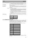
RS-232C SETUP
METHOD Host link Host Link, RS-232C with
no protocol, 1:1 link
master, or 1:1 link slave
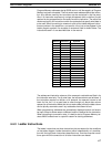
Determines the settings used when a device, such as
a Programmable Terminal or bar code reader is
connected to the RS-232C port.
NODE NO 0 00 to 31
Do not set the node number to a number already used
by another Unit connected in the same
DELAY 0 0 to 9,999 ms
by another Unit connected in the same
communications system (e.g., Host Link System). All
START CODE None 00 to FF
communications
system
(e
.
g
.,
Host
Link
System)
.
All
other settings must match those of the device being
END CODE None 00 to FF or CR, LF
other
settings
must
match
those
of
the
device
being
communicated with.
S tti ff ti i di t l
DATA LINK
AREAS
None LR 00 to LR 63, LR 00 to
LR 31, or LR 00 to LR 15
Settings are effective immediately.
BAUD RATE 9,600 bps 1200, 2400, 4800, 9600,
or 19200
STOP BITS 2 bits 1 or 2 bits
PARITY Even parity Even, odd, or none
DATA LENGTH 7 bits 7 or 8 bits
PC SETUP, HEX
INPUT
Used to set the above parameters on a binary display.
DM Area Section 3-6