


Programming
96 MS-9200UDLS PN 52750:E1 01/27/09
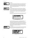
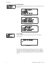
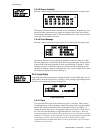
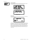
3.6.3.8 Zones Available
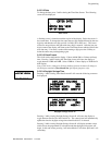
Pressing 2 while viewing Zone Setup Screen #3 will display the following screen:
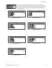
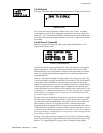
The display will show all of the zones that are still available for programming. Note
that an up and/or down arrow may appear in the upper right corner of the display,
indicating that additional screens of zone information exists. Press the up or down
arrow key to view additional screens.
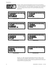
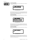
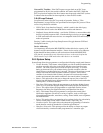
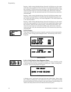
3.6.3.9 Zone Message
Pressing 3 while viewing Zone Setup Screen #3 will display the following screen:
Pressing the down arrow key will display additional screens for Zones up to Z99.
Press the number key corresponding to the Zone to be programmed. Screens will be
displayed allowing the programmer to select Audio Messages 1 through 5. When
an audio message is selected, the display will return to the Zone Message screen,
showing the message selected for that particular zone. In the example above, Zone
01 has been programmed for Audio Message 1.
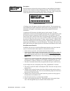
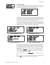
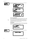
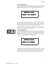
3.6.4 Loop Setup
Loop Setup allows the programmer to configure the SLC Loop for NFPA Style 4, 6 or 7
wiring and to select the loop protocol. Pressing 1 while viewing Programming Screen
#2 will cause the following screen to be displayed:
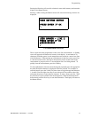
3.6.4.1 Style
To program the SLC Style for the selected loop, press 1 for Style, while viewing
Loop Setup Screen. In the preceding example, the control panel is programmed for
Style 4 SLC wiring as indicated by the 4 to the right of Style in the display. To
change the wiring style, press 1 to toggle the display to read Style 6. Each press of
the 1 key will cause the display to toggle between Style 4 and Style 6. Note that,
when programming the Loop Style, the programmer can only select between Style 4
and Style 6. To program a system for Style 7 wiring, the programmer must select the
Loop Setup for Style 6. Style 7 wiring is the same as Style 6 with the added
requirement that each addressable device on the loop must have a pair of isolator
modules, one on each side.
ZONE SETUP
1=ZONE TYPES
2=ZONES AVAILABLE
3=ZONE MESSAGE
Zone Setup Screen #3
ZONES AVAILABLE
01 02 03 04 05 06 07
08 09 10 11 12 13 14
15 16 17 18 19 20 21
ZONE MESSAGE
1=Z00 NO MESSAGE
2=Z01 MESSAGE 1
3=Z02 NO MESSAGE
PROGRAMMING
1=LOOP SETUP
2=SYSTEM SETUP
3=VERIFY LOOP
Programming Screen #2
LOOP SETUP
1=STYLE 4
2=PROTOCOL LITESPEED
Loop Setup Screen