


Product Description
MS-9200UDLS PN 52750:E1 01/27/09 21
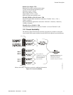
These devices (i.e., MMF-300, MMF-301, MMF-302, CMF-300, CRF-300) can
operate in CLIP mode (Classic Loop Interface Protocol) or LiteSpeed mode to provide
a quicker response. They are also compatible with older 300 series devices. If a mix of
old and new series devices are installed on the same loop, the FACP must be
programmed to operate in CLIP mode. Refer to the SLC Wiring Manual for a list of
compatible addressable modules. Refer to the Device Compatibility Document for a
list of approved conventional notification and initiating devices.
1.6.3 300 Series Intelligent Addressable Devices
Fire-Lite’s 300 Series Intelligent Addressable Devices are fully compatible with the
MS-9200UDLS FACP. The address of 300 Series devices cannot be set above 99.
Refer to the SLC Wiring Manual for a list of compatible addressable devices.
1.6.4 Addressable Device Accessories
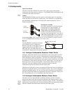
End-of-Line Resistor Assembly
The End-of-Line resistors are included with each module. Refer to the specific module
documentation for specific information.
Power Supervision Relay
The UL listed End-of-Line power supervision relay is used to supervise the power to 4-
wire smoke detectors and notification appliances.
EOL-C(R/W) Mounting Plate
The EOL-CR (red) and EOL-CW (white) are single End-of-Line resistor plates which
are required for use in Canada. An ELR, which is supplied with each module and fire
alarm control panel, is mounted to the EOL-C(R/W) plate. Resistors mounted to the
plate can be used for the supervision of a monitor and control module circuit.
1.7 Optional Modules
The MS-9200UDLS main circuit board includes option module connectors for the
following module:
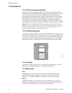
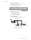
4XTMF Transmitter Module
The 4XTMF provides a supervised output for local energy municipal box transmitter,
alarm and trouble reverse polarity. It includes a disable switch and disable trouble
LED. A jumper on the module is used to select an option which allows the reverse
polarity circuit to open with a system trouble condition if no alarm condition exists.
The module plugs into connectors J5 and J6 which are located near the right edge the
main circuit board. When the 4XTMF module is installed, Jumper JP3, on the main
circuit board, must be cut to allow supervision of the module.