


Product Description
MS-9200UDLS PN 52750:E1 01/27/09 39
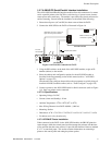
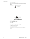
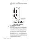
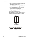
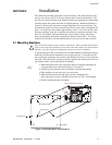
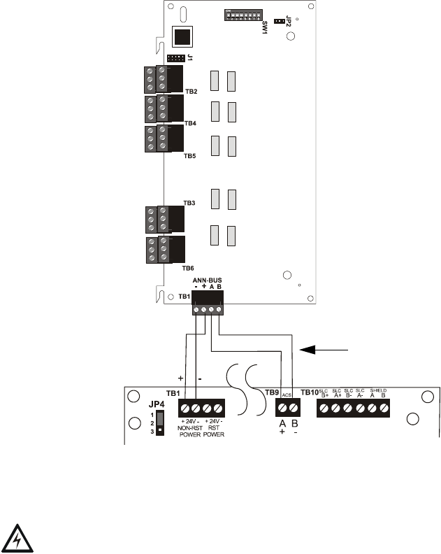
1.8.7.7.4 ANN-RLY Connection to FACP
Figure 1.13 illustrates the ANN-RLY board showing locations of screw terminals
for connection to the FACP and the DIP switches for selecting the ANN-BUS ID
number.
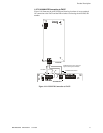
1.8.7.8 ANN-BUS Audio Panel Control
WARNIN G! Disconnect all sources of power (AC and DC) before installing or
removing any wiring.
The FACP is capable of providing automated activation of the ACC-25/50(ZS/T)
zoned system speaker circuits. To do this, the FACP must be enabled to
communicate with the ACC-25/50ZS Audio Panel over the ANN-BUS (refer to
"ANN-BUS Enabled" on page 118). This is accomplished by programming the
Audio Panel ANN-BUS address into the FACP (refer to "Modules Installed" on
page 118). For details on setting the ANN-BUS address and programming the
audio panel, refer to the ACC-25/50ZS Series Audio Panel manual (document
#51889).
The ACC-25/50ZS Series audio panel connects to the FACP via the ACS/ANN-
BUS communication circuit. Zones 33 - 56 on the FACP correspond to the ACC-
25/50ZS Series audio circuits 1 - 24. Zone 32 on the FACP serves as the All-Call
zone and will activate all audio panel output circuits. The programmer can select
which of the five audio messages at the audio panel will play when an FACP input
zone goes into alarm (refer to "Zone Message" on page 96). The message will play
over the corresponding audio panel output circuit.
Figure 1.13 ANN-RLY Connection to FACP
FACP
ANN-RLY
ANN-BUS/ACS BUS
+24 VDC
-24 VDC
ANN-BUS and power wiring are
supervised and power-limited