


Installation
58 MS-9200UDLS PN 52750:E1 01/27/09
A parallel printer may also be connected to the FACP using the optional ANN-S/PG
Serial/Parallel Interface Module. Refer to "ANN-S/PG Serial/Parallel Interface
Installation" on page 31 for installation details. Refer to "ANN-BUS Options" on page
118 for programming information.
CAUTION! Do not connect a printer or PC to the MS-9200UDLS FACP if a ground
fault (zero impedance to ground) exists on the control panel. Circuit damage may
result. Remove all power (Primary and Secondary) before installing or removing any
wiring.
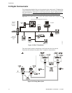
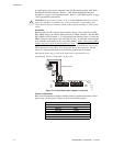
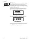
Installation
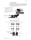
Remote printers and PCs require separate primary power. Also required is the PRT/
PK-CABLE which is an interface cable prewired to a DB9F connector. Wire the PRT/
PK-CABLE to TB8 Terminals 1 - 4 as illustrated in the following figure. Connect the
DB9F connector to the printer or PC serial EIA-232 port. If a nine-pin serial connector
is not available on the printer or PC, use a DB25 adapter. Make certain that the DB25
adapter does not swap the Transmit and Receive lines. Apply power to the FACP and
printer or PC. Note that a ground fault (zero impedance to ground) may occur on the
FACP, dependent on the printer or PC being used, due to this connection. For this
reason, it is important that there be no preexisting ground fault on the panel.
Note that the printer may or may not be supervised as determined by user
programming. Refer to "Printer/PC" on page 142.
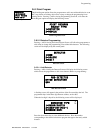
Printer Configuration
Refer to the documentation supplied with the printer for pertinent information about
printer setup. Set the printer’s options as listed in the following table:
COMMUNICATION SETUP
BUFFER: LARGE
DATA BITS: 7
PARITY: EVEN
STOP BIT: 1 STOP
BAUD RATE: 2400/4800/9600
AUTOMATIC LINE FEED NO
AUTOMATIC CARRIAGE RETURN NO
!
PRT/PK-CABLE
92udlstb8.cdr
Figure 2.17 Serial Printer and Computer Connections