


Programming
MS-9200UDLS PN 52750:E1 01/27/09 109
3.6.5.5.6 Zone
A maximum of five zones can be programmed to each main circuit board NAC.
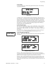
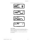
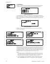
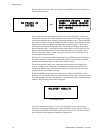
Pressing 1 while viewing NAC Screen #3 displays the following screen:
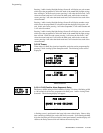
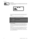
Note that Z** represents the Zone Number(s) corresponding to the selected NAC.
The factory default for an unprogrammed device is Z00 for general alarm zone. A
flashing cursor will appear on the first 0 to the left. Enter the two digit number
corresponding to the zone that is to be assigned to this NAC. The cursor moves to
the next Z** designation. Continue entering zone assignments or the remaining
zones can be left blank or programmed as general alarm zone Z00. When all
desired changes have been made, press the Enter key to store the zone assignments.
The display will return to the NAC Screen #3 which will show the zone assignments
just entered.
3.6.5.5.7 Silence Inhibited
The Silence Inhibit feature, when enabled, prevents the silencing of the selected
main circuit board NAC for a period of one minute. Resetting the FACP will also
be prevented for one minute while the NAC programmed for silence inhibit is
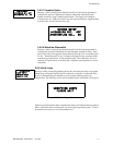
activated. Pressing 2 while viewing NAC Screen #3 will cause the display to
change from the factory default of Silence Inhibit No to Silence Inhibit Yes. Each
press of the 2 key will cause the display to toggle between the two options.
3.6.5.5.8 Sync Type
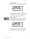
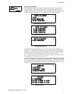
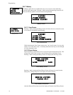
If synchronized strobes were selected as the Type of device installed, the type of
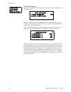
synchronization must be selected in this option. Pressing 1 while viewing NAC
Screen #4 will cause the following screen to be displayed:
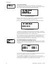
Pressing 1 while viewing this screen will select System Sensor synchronization, 2
will select Wheelock and 3 will select Gentex.
3.6.5.5.8.1 Maximum Number of Strobes for Synchronization
The total current draw for each Notification Appliance Circuit cannot exceed 2.5
amps. Refer to the manufacturer’s documentation supplied with the Strobes to
determine the maximum current draw for each strobe and ensure that the circuit
maximum is not exceeded.
To ensure proper strobe and circuit operation, there is also a limit to the number of
strobes that can be attached to each circuit. Following is a list of the strobes that
have been tested with this FACP and the maximum number that can be connected to
each NAC. Make sure that the NAC maximum current is not exceeded:
System Sensor: 40 Strobes
Wheelock: 25 Strobes
Gentex: 23 Strobes
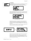
NAC #
1=ZONE
00 00 00 00 00
2=SIL INHIBITED NO
NAC Screen #3
ZONE ASSIGNMENT
Z00 Z** Z** Z** Z**
Zone Screen
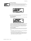
NAC #
1=SYNC TYPE
NAC Screen #4
NAC SYNC TYPE
1=SYSTEM SENSOR
2=WHEELOCK
3=GENTEX